Inductively-powered gas discharge lamp circuit

a technology of inductively powered gas discharge lamps and circuits, which is applied in the direction of lighting devices, electrical equipment, light sources, etc., can solve the problems of reducing the overall cost and size of the circuit, and reducing the risk of direct electrical connections. , the effect of simple and effective circuits

Inactive Publication Date: 2009-09-22
ACCESS BUSINESS GRP INT LLC
View PDF50 Cites 8 Cited by
  • Summary
  • Abstract
  • Description
  • Claims
  • Application Information

AI Technical Summary

Benefits of technology

[0016]The present invention provides a simple and effective circuit and method for pre-heating, starting and powering a gas discharge lamp. The present invention utilizes a minimum number of components to achieve complex functionality. This reduces the overall cost and size of the circuitry. The present invention also provides the potential for improved reliability because it includes a small number of components, the components are passive in nature and there is less complexity in the manner of operation. In typical applications, the system automatically starts (or strikes) the lamp when the primary circuit switches from the pre-heat frequency to the operating frequency. The initial switch causes sufficient voltage to build across the electrodes to permit electricity to arc across the electrodes through the gas. Once the lamp has been started, the impedance through the lamp drops even farther creating a greater difference between the impedance of the electrical path through the lamp and the electrical path through the pre-heat capacitor. This further reduces the amount of current that will flow through the pre-heat capacitor during normal operation. In applications in which the resonant frequency of the primary circuit is selectively adjustable, the primary circuit can be adapted to provide efficient resonant operation during both pre-heat and operation. Further, the components of the secondary circuit can be readily incorporated into a lamp base, thereby facilitating practical implementation.

Problems solved by technology

As current flows through the electrodes, the inherent resistance of the electrodes results in the excitation of electrons.
Although functional, this power supply circuit requires the use of two additional transformers, which dramatically increase the cost and size of the power supply circuit.
Further, direct electrical connections provide a relatively high risk of electrical problems bridging between the power supply and the lamp.
Although an inductive coupling provides a variety of benefits over direct electrical connections, the use of an inductive coupling complicates the starting process.
Although reliable, this starter configuration requires close proximity between the electromagnet and the reed switch.
Collectively, these requirements can place meaningful limitations on the design and configuration of the power supply circuit and the overall lamp circuit.

Method used


Image

  • Inductively-powered gas discharge lamp circuit
  • Inductively-powered gas discharge lamp circuit
  • Inductively-powered gas discharge lamp circuit

Examples


Embodiment Construction

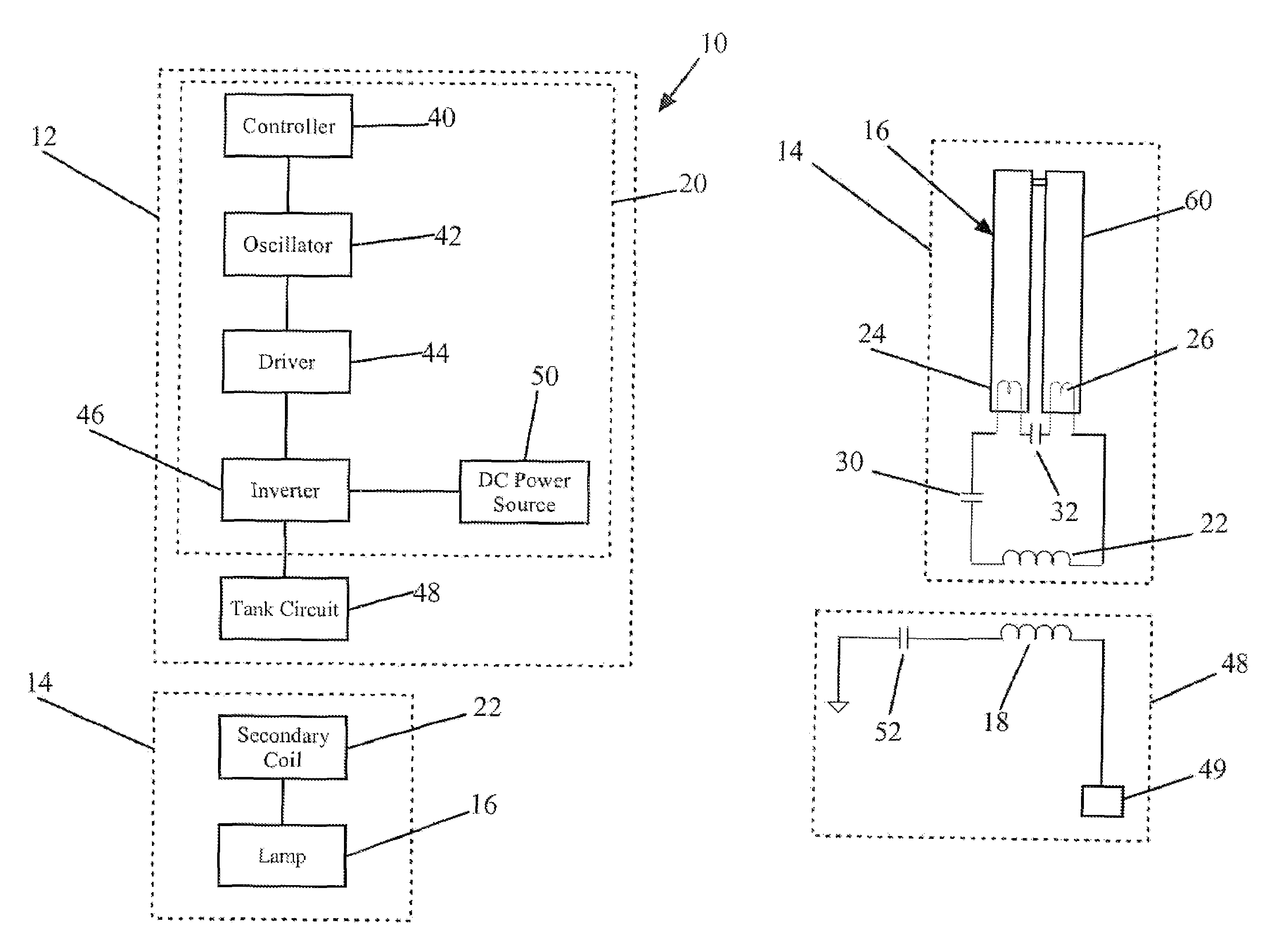
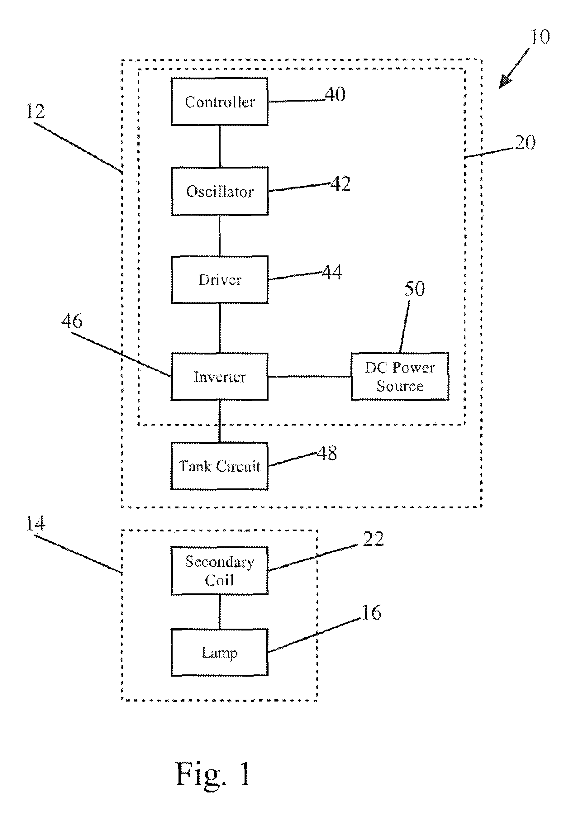
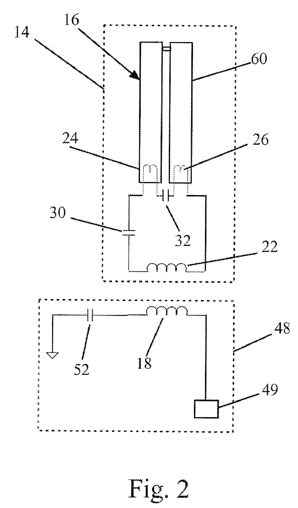
[0024]A gas discharge lamp system 10 in accordance with one embodiment of the present invention is shown in FIG. 1. The gas discharge lamp system 10 generally includes a primary circuit 12 and a secondary circuit 14 powering a gas discharge lamp 16. The primary circuit 12 includes a controller 20 for selectively varying the frequency of the power inductively transmitted by the primary circuit 12. The secondary circuit 14 includes a secondary coil 22 for inductively receiving power from the primary coil 18 and a gas discharge lamp 16. The secondary coil 22 further includes an operating capacitor 30 connected between the secondary coil 22 and the lamp 16 and a pre-heat capacitor 32 connected in series between the lamp electrodes 24 and 26. In operation, the controller 20 pre-heats the lamp 16 by applying power to the secondary circuit 14 at a pre-heat frequency selected so that the impedance of the electrical path through the pre-heat capacitor 32 is less than the impedance of the ele...


PUM


Abstract

An inductively powered gas discharge lamp assembly having a secondary circuit with starter circuitry that provides pre-heating when power is supplied to the secondary circuit at a pre-heat frequency and that provides normal operation when power is supplied to the secondary circuit at an operating frequency. In one embodiment, the starter circuitry includes a pre-heat capacitor connected between the lamp electrodes and an operating capacitor located between the secondary coil and the lamp. The pre-heat capacitor is selected so that the electrical flow path through the pre-heat capacitor has a lesser impedance than the electrical flow path through the gas of the lamp when power is applied to the secondary circuit at the pre-heat frequency, and so that the electrical flow path through the pre-heat capacitor has a greater impedance than the electrical flow path through the gas when power is applied the operating frequency. The primary circuit may include a tank circuit for which the resonant frequency can be adjusted to match the pre-heat frequency and the operating frequency.

Description

BACKGROUND OF THE INVENTION[0001]The present invention relates to gas discharge lamps, and more particularly to circuits for starting and powering gas discharge lamps.[0002]Gas discharge lamps are used in a wide variety of applications. A conventional gas discharge lamp includes a pair of electrodes spaced apart from one another within a lamp sleeve. Gas discharge lamps are typically filled with an inert gas. In many applications, a metal vapor is added to the gas to enhance or otherwise affect light output. During operation, electricity is caused to flow between the electrodes through the gas. This causes the gas to discharge light. The wavelength (e.g. color) of the light can be varied by using different gases and different additives within the gas. In some applications, for example, conventional fluorescent lamps, the gas emits ultraviolet light that is converted to visible light by a fluorescent coating on the interior of the lamp sleeve.[0003]Although the principles of operatio...

Claims


Application Information

Patent Timeline
Patent Type & Authority Patents(United States)
IPC IPC(8): H05B41/16
CPCH05B41/2822H05B41/24
Inventor BAARMAN, DAVID W.MOLLEMA, SCOTT A.
Owner ACCESS BUSINESS GRP INT LLC
Why Eureka
Try Eureka