Start-up circuit with feedforward compensation for power converters

a technology of power converters and start-up circuits, applied in the field of power converters, can solve the problems of significant power loss, insufficient application of skill innovations in906,934 to the apparatus of u.s. pat. no. 6,611,439, and affect the maximum output power, so as to save power and reduce the number of devices

Active Publication Date: 2009-09-22
SEMICON COMPONENTS IND LLC
View PDF4 Cites 19 Cited by
  • Summary
  • Abstract
  • Description
  • Claims
  • Application Information

AI Technical Summary

Problems solved by technology

However, the maximum output power is affected by a response time TD.
Because the resistors 30 and 35 will cause significant power loss, especially in high line voltage input.
However, the skill innovated in U.S. Pat. No. 6,906,934 is inadequate to be applied to the apparatus of U.S. Pat. No. 6,611,439.

Method used


Image

  • Start-up circuit with feedforward compensation for power converters
  • Start-up circuit with feedforward compensation for power converters
  • Start-up circuit with feedforward compensation for power converters

Examples


Embodiment Construction

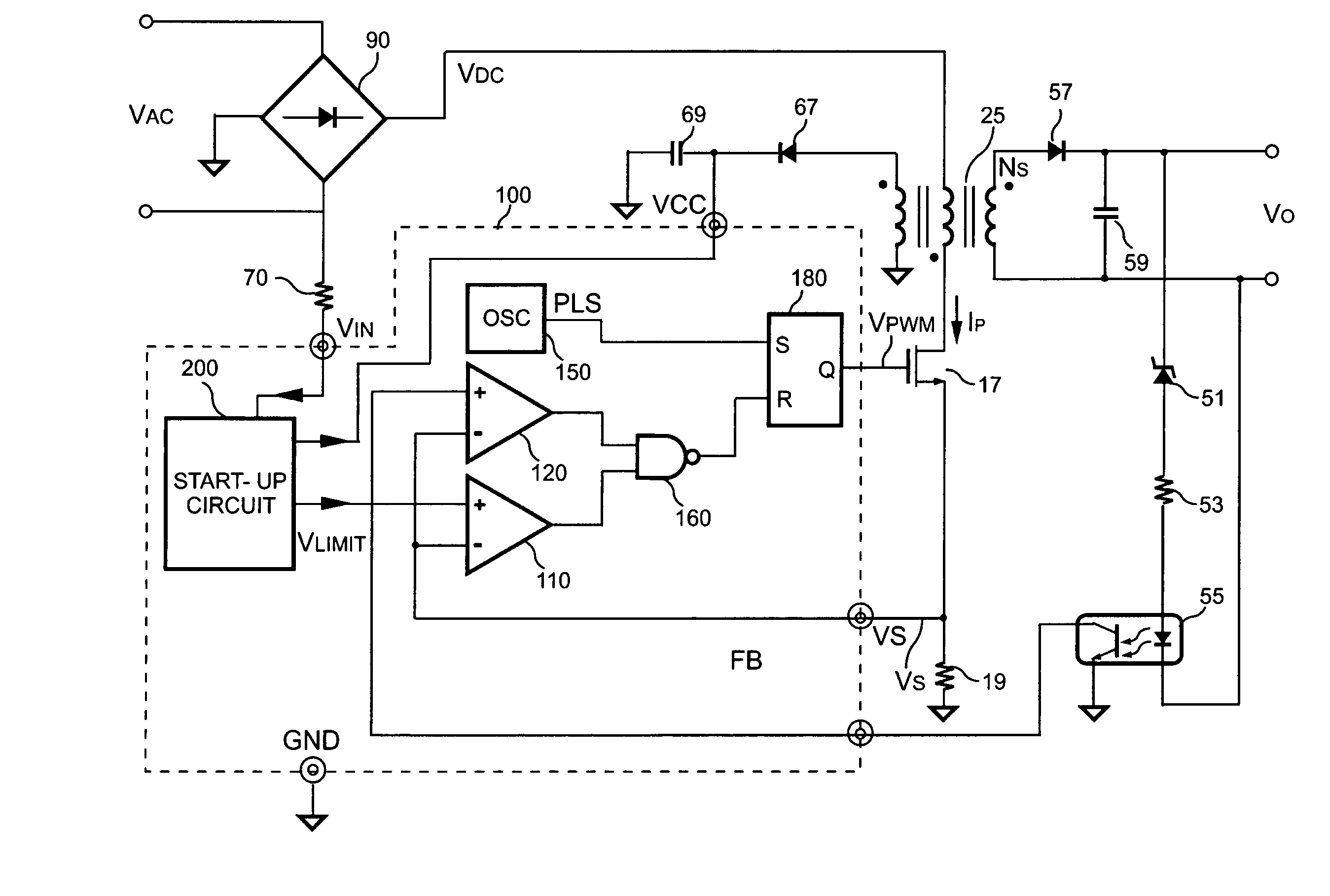
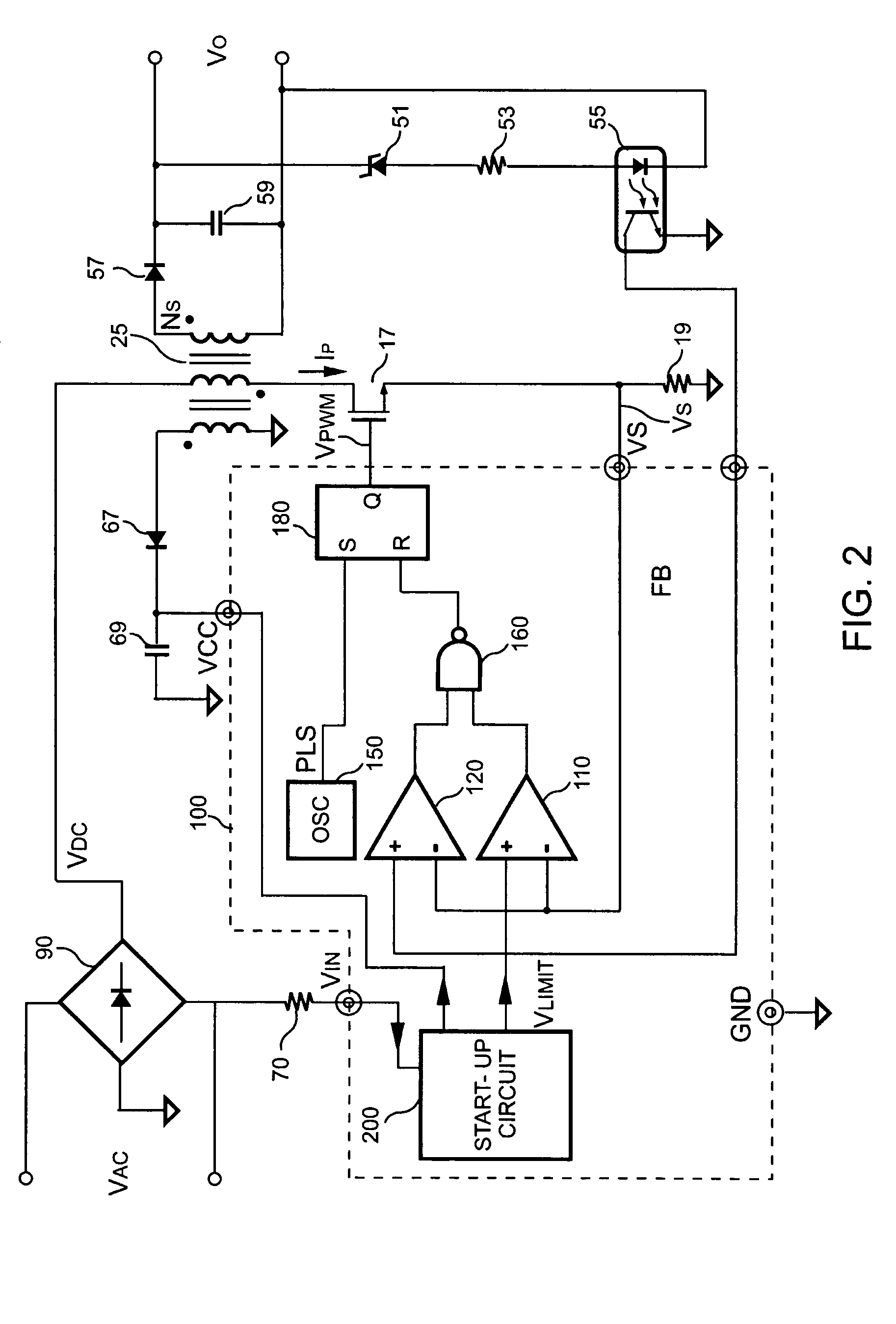
[0014]FIG. 2 schematically shows a switching power converter according to the present invention. A control circuit 100 comprises a start-up circuit 200, a first comparator 110, a second comparator 120, a NAND gate 160, a flip-flop 180 and an oscillator 150, which serve to provide a pulse signal PLS for the flip-flop 180. A bleeding resistor 70 is required to discharge EMI filter of the power converter for the safety purpose. In order to save power and reduce device count, the present invention further uses the bleeding resistor 70 for both start-up and feedforward compensation. The bleeding resistor 70 is connected between an input voltage VAC and an input terminal VIN of the control circuit 100 for the start-up. A bridge circuit 90 is coupled between the input voltage VAC and the bleeding resistor 70. The bridge circuit 90 is further coupled to the primary winding of a transformer 25. Once the power converter is turned on, the input voltage VAC is applied to the start-up circuit 20...


PUM


Abstract

A bleeding resistor is required to discharge EMI filter of the power converter for the safety purpose. In order to save power and reduce device count, the present invention further uses this bleeding resistor for both start-up and feedforward compensation. It includes an input terminal for connecting the bleeding resistor. A voltage divider is connected to the input terminal. A sample-and-hold circuit samples and holds a voltage signal from the voltage divider. After that, a low-pass filter is connected to the sample-and-hold circuit to generate an offset signal in accordance with the voltage signal. The offset signal is connected to a limit circuit to generate a limit signal that limits the switching current of the power converter.

Description

BACKGROUND OF THE INVENTION[0001]1. Field of the Invention[0002]The present invention relates to power converters. More particularly, the present invention relates to the control circuit of switching power converters.[0003]2. Background of the Invention[0004]The switching power converter is a traditional technology to control the output power and achieve the regulation. Various protection functions, such as over-voltage and over-current protection are built-in in the power converter to protect the power converter and the connected circuits from permanent damage. The function of output power limit is generally used for the over-load and short circuit protection. Referring to FIG. 1, a traditional switching power converter uses a control circuit 50. The operation of the power converter starts on the charging of a start-up capacitor 65 coupled to the supply terminal VCC of the control circuit 50 via a serial start-up resistor 30 for providing a supply voltage VCC by an input voltage VD...

Claims


Application Information

Patent Timeline
Patent Type & Authority Patents(United States)
IPC IPC(8): G05F1/573
CPCH02M1/36H02M2001/0019H02M1/0019Y10S323/908
Inventor YANG, TA-YUNG
Owner SEMICON COMPONENTS IND LLC
Why Eureka
Try Eureka