LAN switch with rapid fault recovery

a fault recovery and lan switch technology, applied in the field of computer networking, can solve problems such as link failure detection, unusable loops, and confusion of forwarding algorithms, and achieve the effect of rapid fault recovery

Active Publication Date: 2009-09-22
GARRETTCOM
View PDF19 Cites 24 Cited by
  • Summary
  • Abstract
  • Description
  • Claims
  • Application Information

AI Technical Summary

Benefits of technology

[0011]Another embodiment of the invention relates to a network that includes a plurality of Ethernet switches in a redundant topology. At least one switch is configured to implement a link-loss-learn protocol for rapid fault recovery.

Problems solved by technology

Undesirable loops occur when there are multiple active paths between stations.
This can confuse the forwarding algorithm, allowing duplicate frames to be forwarded.
A link failure is detected at a port of the switch.
In addition, a link on another port of the switch may be dropped to propagate the link failure.

Method used


Image

  • LAN switch with rapid fault recovery
  • LAN switch with rapid fault recovery
  • LAN switch with rapid fault recovery

Examples


Embodiment Construction

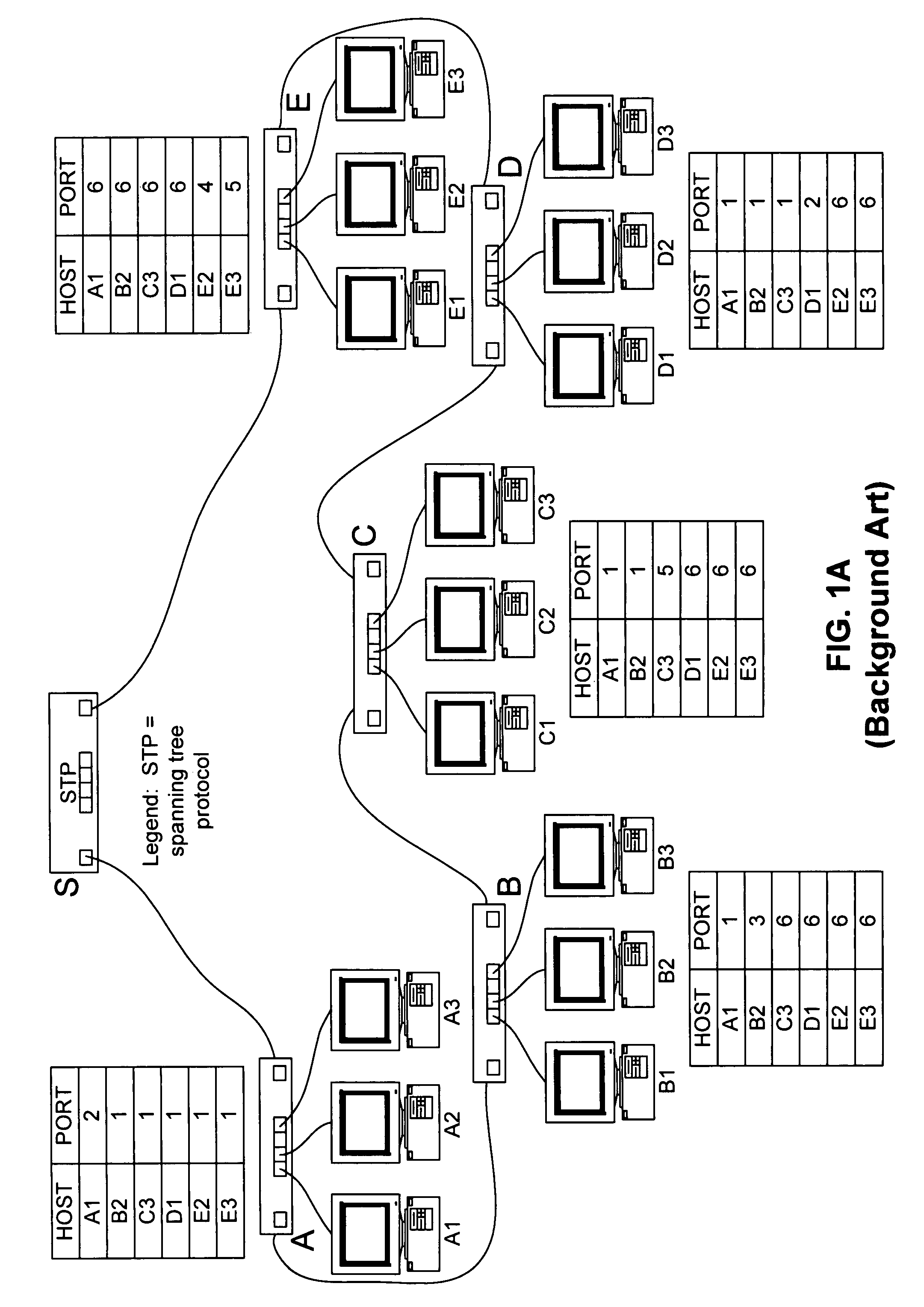
[0016]FIG. 1A is a diagram depicting a simple network topology for discussion purposes. Depicted are a number of networking switches S, A, B, C, D, and E. In this example, the switches are interconnected together in a ring topology. Switch S may be particularly configured to implement STP.

[0017]Various hosts are shown connected to switch ports. Hosts A1, A2, and A3 are shown as connected to ports of switch A, hosts B1, B2, and B3 are shown as connected to ports of switch B, and so on. In addition, example Media Access Control (MAC) address tables in some of the switches are illustrated. For example, the address table in switch A has host address A1 associated with port 2, and host addresses B2, C3, D1, E2, and E3 each associated with port 1.

[0018]Such a ring should have a port somewhere in the series that operates in a “blocked” mode. Such a blocked port does not pass packets so that a correct Ethernet topology without looping exists. The control of which port is blocked is determin...


PUM


Abstract

One embodiment disclosed relates to a method of fault recovery by a switch in a local area network. A link failure is detected at a port of the switch. In response to the link failure detection, a medium access control (MAC) address table of the switch is cleared. Clearing the address table causes a discovery process to fill the table to begin immediately. In addition, a link on another port of the switch may be dropped to propagate the link failure.

Description

RELATED APPLICATIONS[0001]The present application claims the benefit of U.S. provisional patent application No. 60 / 418,896, filed Oct. 15, 2002, entitled “System and method for operation of managed ethernet LAN switch products in redundant network configurations with fast recovery from faults,” the disclosure of which is hereby incorporated by reference in its entirety.[0002]In addition, the present application claims the benefit of U.S. provisional patent application No. 60 / 467,273, filed May 2, 2003, entitled “System and method for S-Ring, a fast recovery enhancement to spanning tree protocol,” the disclosure of which is hereby incorporated by reference in its entirety.NOTICE REGARDING COPYRIGHTED MATERIAL[0003]A portion of the disclosure of this patent document contains material which is subject to copyright protection. The copyright owner has no objection to the facsimile reproduction by anyone of the patent document or the patent disclosure as it appears in the Patent and Trade...

Claims


Application Information

Patent Timeline
Patent Type & Authority Patents(United States)
IPC IPC(8): G06F11/00G08C15/00
CPCH04L12/462H04L49/557H04L49/351
Inventor SIVASANKARAN, DILEEPMADREN, FRANK S.WOOD, PETER R.
Owner GARRETTCOM
Why Eureka
Try Eureka