Drying mode for automatic clothes dryer

a clothes dryer and automatic technology, applied in the direction of dryers, dryers with progressive movements, instruments, etc., can solve the problems of excessive shrinkage or damage, overheating of clothes, and excessive energy consumption

Active Publication Date: 2009-09-29
WHIRLPOOL CORP
View PDF99 Cites 52 Cited by
  • Summary
  • Abstract
  • Description
  • Claims
  • Application Information

AI Technical Summary

Problems solved by technology

However, conventional dryers will continue to operate through a preselected cycle without modification based upon the predetermined drying time, which can result in overheating of the clothes, with accompanying excessive shrinkage or damage, excess energy usage, and increased wear on the dryer components.

Method used


Image

  • Drying mode for automatic clothes dryer
  • Drying mode for automatic clothes dryer
  • Drying mode for automatic clothes dryer

Examples


Embodiment Construction

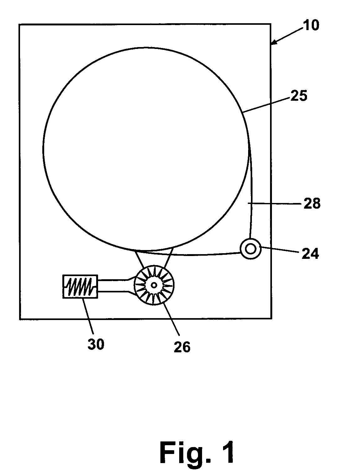
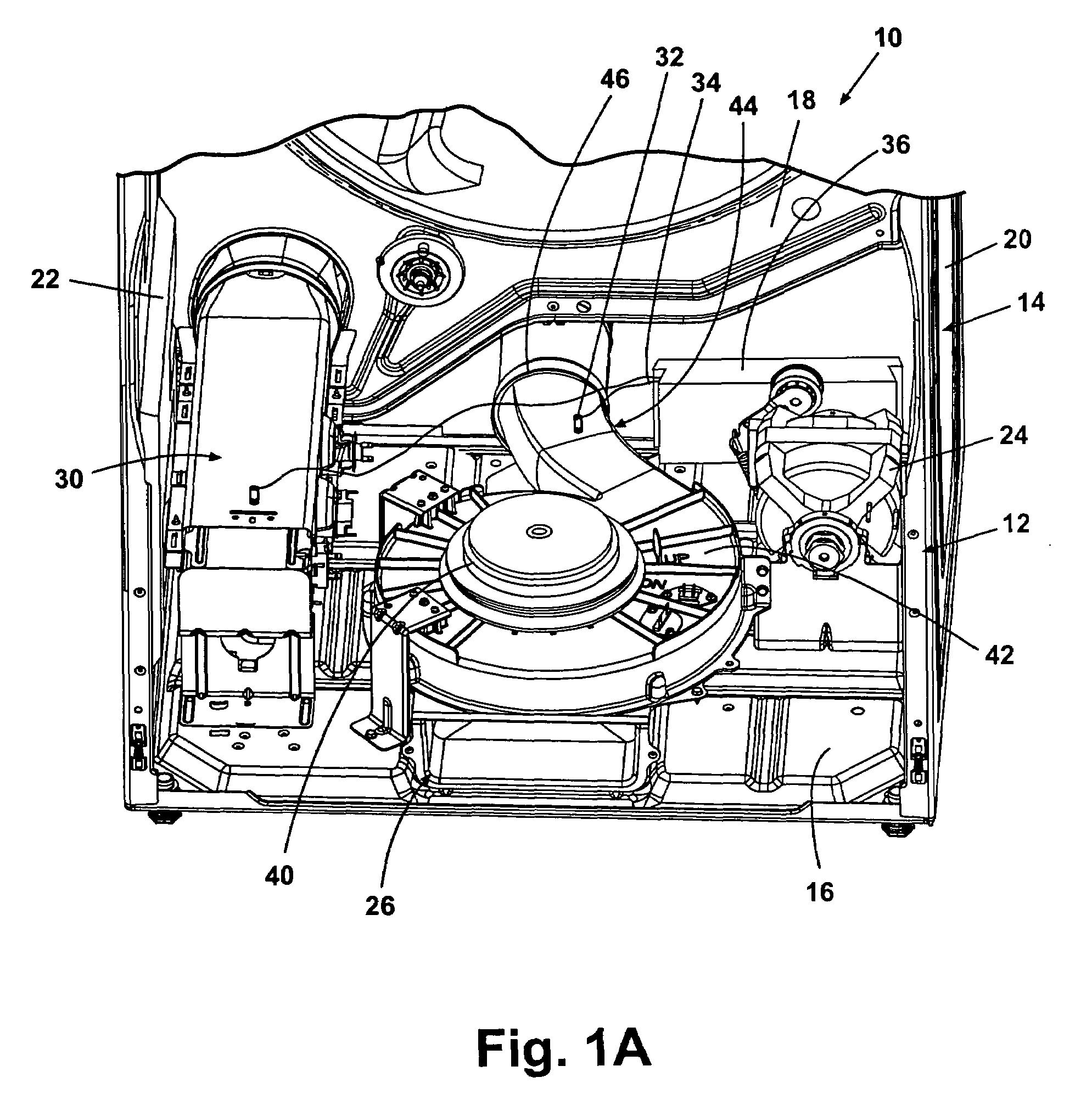
[0020]Referring now to the Figures, and to FIG. 1A in particular, an automatic clothes dryer 10 illustrating one embodiment of the invention is shown comprising a cabinet 14, a rotating drum 25 for holding items to be dried, a motor for rotating the drum 25, and an endless drive belt 28 coupling the drum 25 with the motor 24. These elements are generally well-known and will not be described further herein except as necessary for a complete understanding of the invention. A lower portion of the interior of the dryer 10 is illustrated in a partially cut-away view in FIG. 1A to show the internal structure and components of the dryer 10. A support frame 12 is enclosed by the cabinet 14 in a well-known configuration. The cabinet 14 comprises a floor 16, a back wall 18, and side walls 20, 22. The cabinet 14 also comprises a front wall, which is not shown in the Figures. The cabinet 14 encloses the motor 24 and a blower assembly 26. The motor 24 rotates the drum 25, which is adapted to hol...


PUM


Abstract

A method of drying clothes in a clothes dryer comprising a clothes chamber for receiving clothes, an air supply system for directing air through the clothes chamber, and a heater for heating the air supplied by the air supply system. The method comprises cycling the heater between an ON state by energizing the heater until a heater trip condition is met and an OFF state by deenergizing the heater until a heater reset condition is met, determining a heater off time by determining the time between the heater trip condition and the heater reset condition, and determining a drying time based on the heater off time.

Description

BACKGROUND OF THE INVENTION[0001]1. Field of the Invention[0002]The invention relates generally to automatic clothes dryers, and, more particularly the invention relates to a method of determining a drying time for an automatic clothes dryer.[0003]2. Description of the Related Art[0004]Automatic clothes dryers are well known, and typically comprise a cabinet enclosing a horizontally rotating drum accessible through an access door at the front of the cabinet for holding clothing items to be dried. A heater positioned in an air inlet assembly upstream of the drum is utilized for heating the drying air prior to its entry into the drum. The drying air is delivered to the drum through a motor-driven blower assembly. A temperature sensor is utilized in an air outlet assembly downstream of the drum for monitoring the temperature of the exhausted air and determining when drying is complete.[0005]During the drying cycle, the heater is sequentially energized and deenergized to increase and de...

Claims


Application Information

Patent Timeline
Patent Type & Authority Patents(United States)
IPC IPC(8): F26B3/00D06F58/46
CPCD06F58/28D06F2058/2893D06F2105/28D06F58/46D06F2101/00D06F2105/56D06F2103/38D06F2103/32D06F2103/34
Inventor WOERDEHOFF, CHRISTOPHER JOHNRECK, ANDREW CHARLESKMET, DAVID JOHNSWANSON, JAMES FREDERICK
Owner WHIRLPOOL CORP
Why Eureka
Try Eureka