

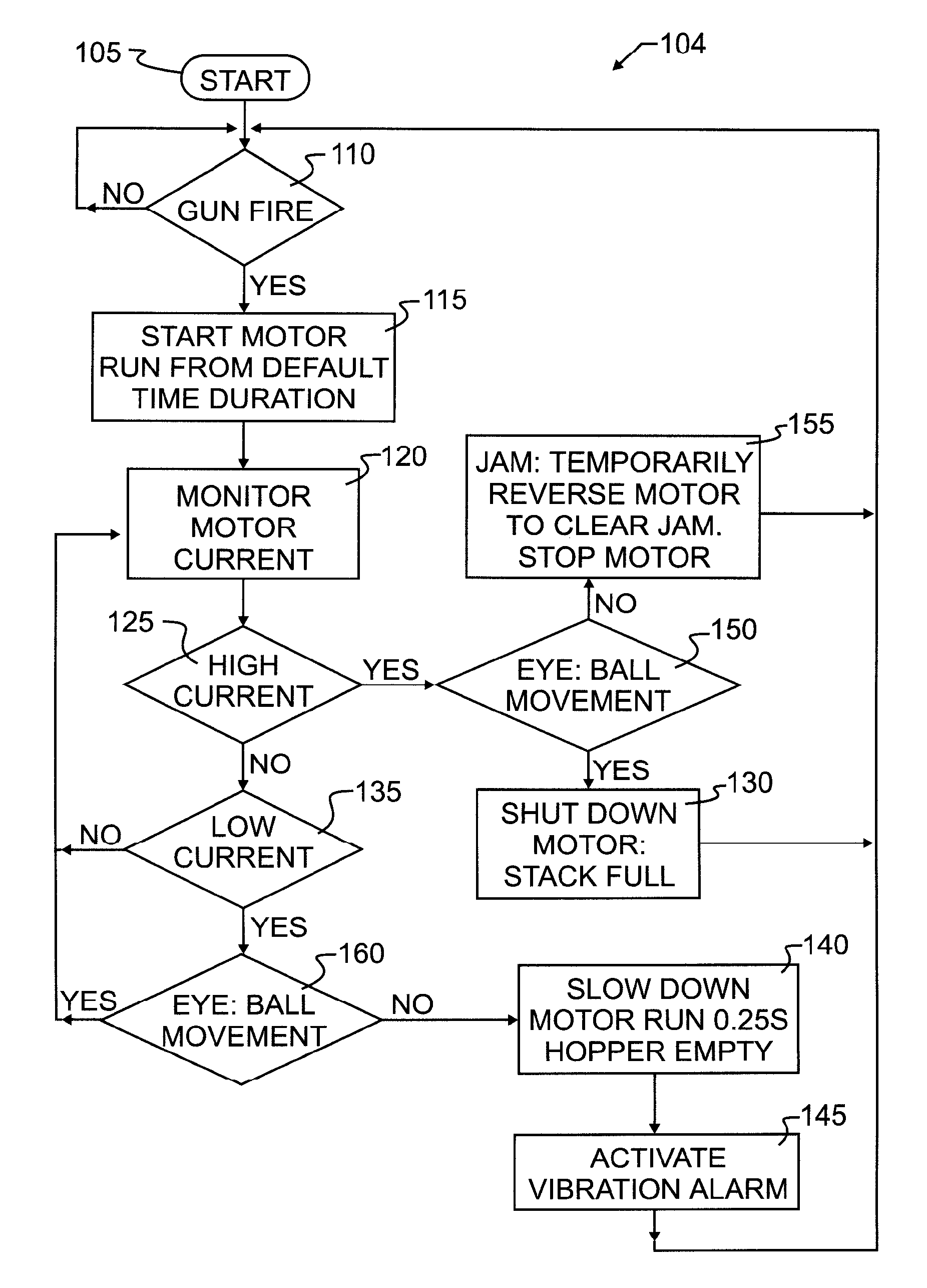
Projectile loading, firing and warning system
- Summary
- Abstract
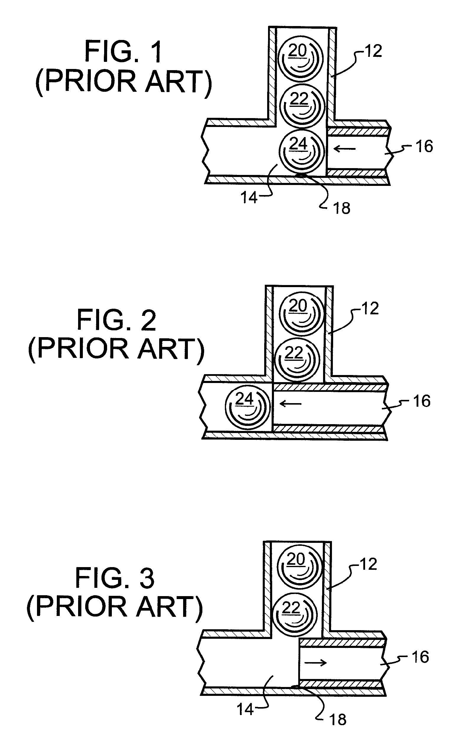
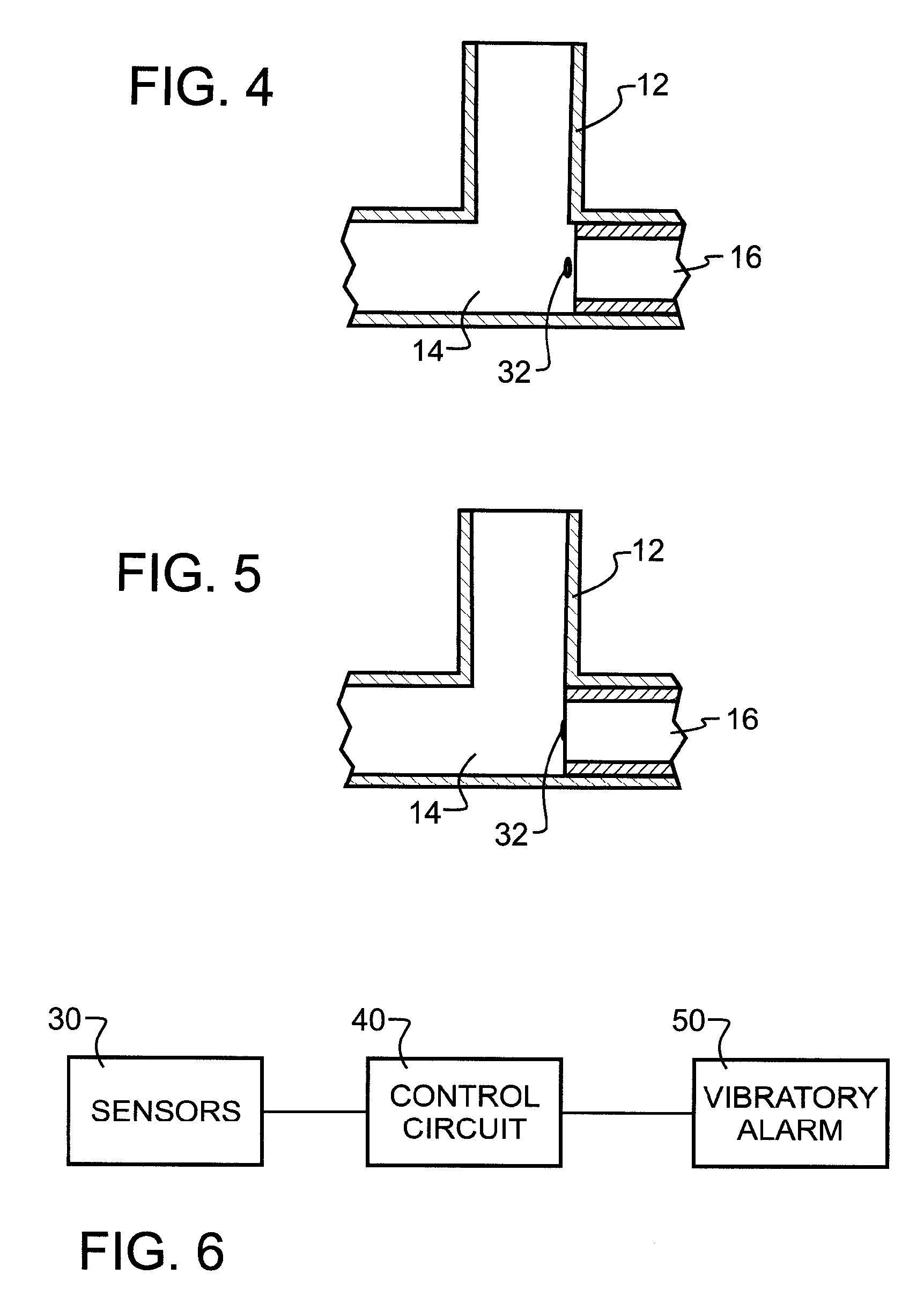
- Description
- Claims
- Application Information
AI Technical Summary
Benefits of technology
Problems solved by technology
Method used
Image

Examples
example 1
Measured Time Intervals
Abort time=4 mS
Start Load Time=8 milliseconds. This indicates a force hopper feed, and the ball in middle breech is detected. Timing consistent with previous shots.
[0075]Final Load Time=7 milliseconds (Measured from previous shot)=Expected time for ball to cross from first sensor 36 until crossing bottom sensor 18. Bolt lag=13 milliseconds=Measured 15 milliseconds but we know that usually 2 milliseconds less for bolt 16 to begin moving.
Aggressive approach: History shows load times of 7 milliseconds and current timing thus far shows force-feeding with consistent load timing. Start pre-energizing solenoid at time ball reaches middle sensor 36. At about 7 milliseconds (if consistent with last shot), the ball will reach bottom sensor 18 and 6 milliseconds later bolt 16 will start moving forward. So there would about 6 milliseconds extra load time, if needed.
Safe approach: Since abort time is 4 milliseconds, start pre-energizing solenoid 2 milliseconds before expec...
example 2
Using a Look Up Table within the Circuit Controller
Measured Time Intervals:
Abort time=4 milliseconds
Start Load Time=13 milliseconds=Force-feed hopper detected and ball in middle breech detected. Timing not consistent with previous shot.
[0076]Final Load Time=Expected time for ball to cross first sensor 36 until crossing bottom sensor 18. Since start load time is inconsistent, can't use last final load time. Must use expected final load time from historical look-up tables. In the past, from the look-up tables, 13 milliseconds start load time may lead to a 20 millisecond final load time.
Bolt lag=13 milliseconds=Measured 15 milliseconds but we know that usually 2 milliseconds less for bolt 16 to begin moving.
Aggressive approach: History shows start load times of 13 milliseconds leads to 20 milliseconds final load times and current timing thus far showing force-feeding. Start pre-energizing solenoid 9 milliseconds after ball reaches middle sensor 36. In another 11 milliseconds (if consis...
example 3
[0081]1. Hopper is full, 150 paintball capacity, and counter is at 150 after turning on marker for a game.[0082]2. 125 paintballs are shot and warning alarm goes off. 25 balls left in hopper.[0083]3. User then refills hopper and resets counter by pressing button (or holding trigger)[0084]4. Hopper is full, 150 paintballs and counter is at 150.
PUM
 Abstract
Description
Claims
Application Information