Method for fabricating a spacer layer for a magnetoresistive element

a technology of magnetoresistive elements and spacer layers, applied in the field of magnetic recording technology, can solve the problems of poor signal from such tmr elements, too high for device applications, adversely affecting the insulating nature of conventional barrier layers, etc., and achieve the effect of reducing and repeating the magnetostriction

Inactive Publication Date: 2009-09-29
WESTERN DIGITAL TECH INC
View PDF15 Cites 154 Cited by
  • Summary
  • Abstract
  • Description
  • Claims
  • Application Information

AI Technical Summary

Benefits of technology

[0009]According to the method and system disclosed herein, the present invention provides a method and system for fabricating a magnetoresistive element that can have reduced and repeatable magnetostriction.

Problems solved by technology

However, at such thicknesses of the conventional barrier layer 18, the conventional TMR element 10 may have an RA (resistance multiplied by cross-sectional area) that is too high for device applications.
It is believed that the loss of TMR in such a thin conventional barrier layer 18 is due to defects, such as pinholes, which adversely affect the insulating nature of the conventional barrier layer 18.
Consequently, the signal from such TMR elements is poor.

Method used


Image

  • Method for fabricating a spacer layer for a magnetoresistive element
  • Method for fabricating a spacer layer for a magnetoresistive element
  • Method for fabricating a spacer layer for a magnetoresistive element

Examples


Embodiment Construction

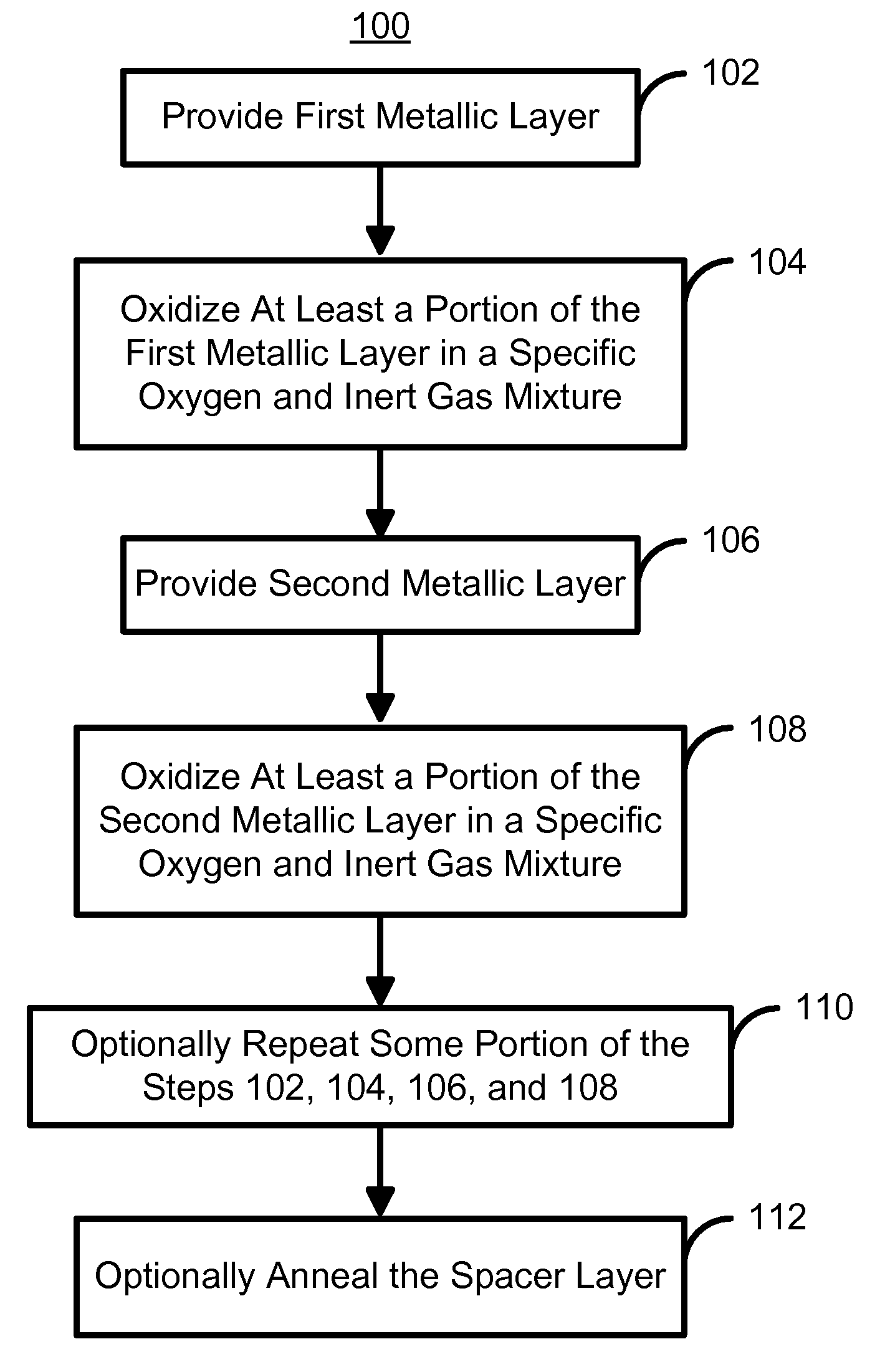
[0019]FIG. 4 depicts a high-level flow chart of a method 100 for fabricating a spacer layer magnetoresistive element, such as a TMR element, according to a preferred exemplary embodiment of the present invention. However, the method 100 might also be for manufacturing other magnetoresistive elements, including but not limited to current-perpendicular-to-plane (CPP) giant magnetoresistance (GMR) elements. The method 100 preferably commences after a portion of the magnetoresistive element has been fabricated. For example, for a structure having a bottom-pinned layer, the method 100 commences after the pinned layer has been fabricated but before the free layer has been provided. Alternatively, for a top pinned structure, the method 100 might start after the free layer has been provided but before the pinned layer has been fabricated.

[0020]A first metallic layer is provided, via step 102. A number of different metals might be used for step 102. For a TMR element, the metallic layer migh...


PUM

PropertyMeasurementUnit
thicknessaaaaaaaaaa
thicknessaaaaaaaaaa
thicknessaaaaaaaaaa

Abstract

A method and system for manufacturing a spacer layer in a magnetoresistive element are described. The spacer layer resides between a free layer and a pinned layer. The method and system include providing a first metallic layer and oxidizing the first metallic layer in a first environment including at least oxygen and a first gas inert with respect to the first metallic layer. The method and system further include providing a second metallic layer and oxidizing the second metallic layer in a second environment including at least oxygen and a first gas inert with respect to the first metallic layer.

Description

FIELD OF THE INVENTION[0001]The present invention relates to magnetic recording technology, and more particularly to a method and system for providing a tunneling magnetoresistive element that has an improved spacer layer between a free layer and a pinned layer.BACKGROUND OF THE INVENTION[0002]FIG. 1 depicts a conventional tunneling magnetoresistive (TMR) element 10. The conventional TMR element 10 includes a seed layer 12, an antiferromagnetic (AFM) layer 14, a conventional pinned layer 16, a conventional barrier layer 18, a conventional free layer 20, and a capping layer 22. The conventional pinned layer 16 may a synthetic pinned layer including two ferromagnetic layers (not shown) separated by a nonmagnetic conductive spacer layer (not shown) that is typically Ru. Similarly, the conventional free layer 20 be a multilayer structure including, but not limited to a synthetic free layer including two ferromagnetic layers (not shown) separated by a nonmagnetic conductive spacer layer ...

Claims


Application Information

Patent Timeline
Patent Type & Authority Patents(United States)
IPC IPC(8): G11B5/33
CPCB82Y10/00B82Y25/00G01R33/098G11B5/3163G11B5/3906G11B5/3909G11B5/3983H01L43/08H01L43/12H01F10/3259G11B5/398Y10T29/49021H01F10/3272H10N50/10H10N50/01
Inventor MOON, KI-SEOKPARK, CHANG-MAN
Owner WESTERN DIGITAL TECH INC
Why Eureka
Try Eureka