Magneto-resistance effect element having free layer including magnetostriction reduction layer and thin-film magnetic head

a technology of resistance effect and free layer, applied in the field of magnetostriction reduction layer and thin-film magnetic head, can solve the problems of undesirable lowering of waveform symmetry, difficult to employ comnge film in the free layer, and inability to achieve desired reading performance of thin-film magnetic head incorporating mr element, etc., to achieve reduced magnetostriction of heusler alloy layer, high mr ratio, and high spin polarizability

Inactive Publication Date: 2010-07-20
TDK CORPARATION
View PDF12 Cites 1 Cited by
  • Summary
  • Abstract
  • Description
  • Claims
  • Application Information

AI Technical Summary

Benefits of technology

[0016]It is an object of the present invention to provide a magnetoresistance effect element and a thin-film magnetic head in which a Heusler alloy layer, which exhibits a high spin polarizability even if it is annealed at a relatively low temperature, can be employed in a free layer and therefore a high MR ratio can be achieved by a reduction of the magnetostriction of the Heusler alloy layer.
[0018]With the above arrangement, since the magnetostriction of the free layer is reduced by the magnetostriction reduction layer, the characteristics such as waveform symmetry, etc., are prevented from being lowered. As a result, the Heusler alloy layer can be incorporated in the free layer, contributing to an increase in the MR ratio of the magnetoresistance effect element.
[0022]The magnetoresistance effect element should preferably has been annealed at a temperature of 290° C. or lower. In this case, the characteristics of a thin-film magnetic head are prevented from being degraded by heat, and the annealing facility and the annealing process are simplified.

Problems solved by technology

However, if the free layer whose magnetization direction is variable, depending on the external magnetic field, has a high level of magnetostriction, then the waveform symmetry is undesirably lowered.
However, if the asymmetry of an MR element is large (as indicated by the two-dot-and-dash-line curves in FIG. 1), then a thin-film magnetic head incorporating the MR element fails to provide a desired reading performance.
It has thus been practically difficult to employ a CoMnGe film in the free layer.

Method used


Image

  • Magneto-resistance effect element having free layer including magnetostriction reduction layer and thin-film magnetic head
  • Magneto-resistance effect element having free layer including magnetostriction reduction layer and thin-film magnetic head
  • Magneto-resistance effect element having free layer including magnetostriction reduction layer and thin-film magnetic head

Examples


Embodiment Construction

[0037]Hereinafter, embodiments of the present invention will be described below with reference to the drawings.

[Configuration of Thin-Film Magnetic Head]

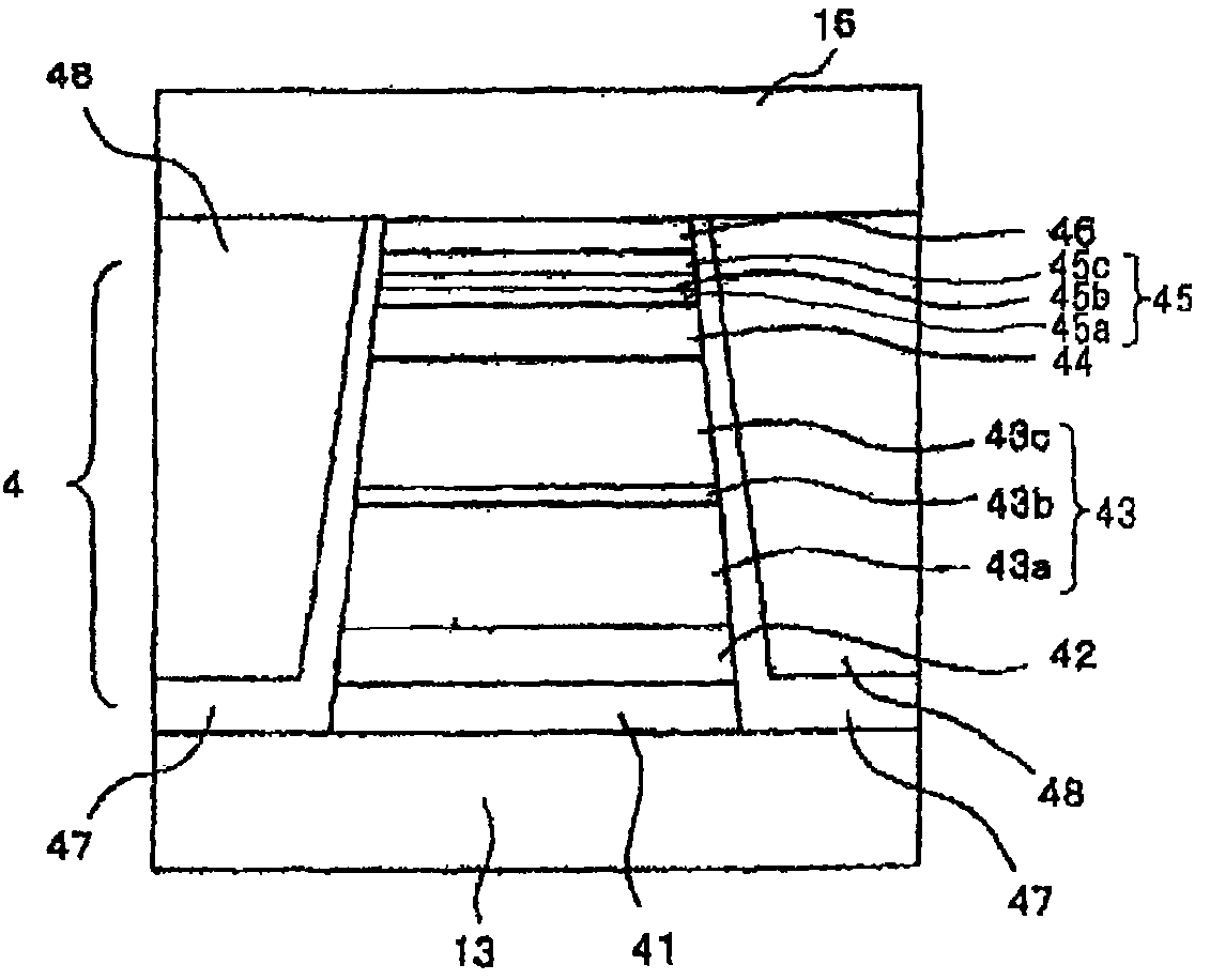
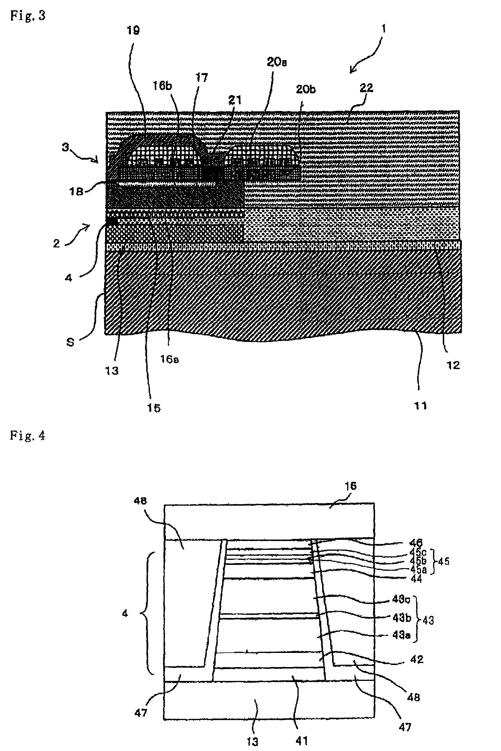
[0038]FIG. 3 conceptually shows a cross-sectional view of a major portion of a thin-film magnetic head having a magneto-resistance effect element according to the present invention.

[0039]Thin-film magnetic head 1 according to the present embodiment has substrate 11, reproducing unit 2 which reads data from a recording medium (not shown) and which is formed on substrate 11, and recording unit 3 for writing data on a recording medium (not shown) and which is formed on substrate 11.

[0040]Substrate 11 is made of Al2O3—TiC (AlTiC) that has excellent wear resistance. Base layer 12 made of alumina is disposed on an upper surface of substrate 11, and reproducing unit 2 and recording unit 3 are stacked on base layer 12.

[0041]Lower shield layer 13 made of a magnetic material such as Permalloy (NiFe), for example, is disposed on base layer 12....


PUM

PropertyMeasurementUnit
thicknessaaaaaaaaaa
temperatureaaaaaaaaaa
thicknessaaaaaaaaaa

Abstract

A magnetoresistance effect element includes a pinned layer having a fixed magnetization direction, a free layer having a magnetization direction variable depending on an external magnetic field, and a nonmagnetic spacer layer disposed between the pinned layer and the free layer. The free layer includes a Heusler alloy layer and a magnetostriction reduction layer made of a 4th group element, a 5th group element, or a 6th group element.

Description

BACKGROUND OF THE INVENTION[0001]1. Field of the Invention[0002]The present invention relates to a magneto-resistance effect element and a thin-film magnetic head.[0003]2. Description of the Related Art[0004]Magnetic disk drives employ a thin-film magnetic head having a magneto-resistance effect element (MR element) for reading magnetic signals. In recent years, efforts have been made to design magnetic disk drives for higher recording densities, and accordingly there are growing demands for thin-film magnetic heads, particularly magneto-resistance effect elements, which satisfy higher-sensitivity and higher-output requirements.[0005]A CIP-GMR (Current in Plane-Giant Magneto-resistance) element which is a giant magneto-resistance effect element having a nonmagnetic layer between ferromagnetic layers and passing a sensing current in parallel to a layer surface, has been conventionally developed as a reproducing element in a thin-film magnetic head. On the other hand, a magnetic head ...

Claims


Application Information

Patent Timeline
Patent Type & Authority Patents(United States)
IPC IPC(8): G11B5/127
CPCB82Y25/00G01R33/093G01R33/18H01F10/1936H01F10/3272H01F10/3295G11B5/3906Y10T428/1107
Inventor MIZUNO, TOMOHITOTSUCHIYA, YOSHIHIROHIRATA, KEI
Owner TDK CORPARATION
Why Eureka
Try Eureka