
Magnetic detection head and method for manufacturing the same

a technology of magnetic detection head and manufacturing method, which is applied in the field of magnetic detection element, can solve the problem of reducing the magnetic force of the above-described free magnetic layer, and achieve the effect of reducing the magnetic force of the free magnetic layer

Active Publication Date: 2010-06-15
TDK CORPARATION
View PDF13 Cites 1 Cited by
  • Summary
  • Abstract
  • Description
  • Claims
  • Application Information

AI Technical Summary

Benefits of technology

[0015]The present invention has been made to overcome the above-described known problems. Accordingly, it is an object of the present invention to provide a magnetic detection element capable of maintaining the ΔRA at a high level and reducing the magnetostriction, as well as a method for manufacturing the same.
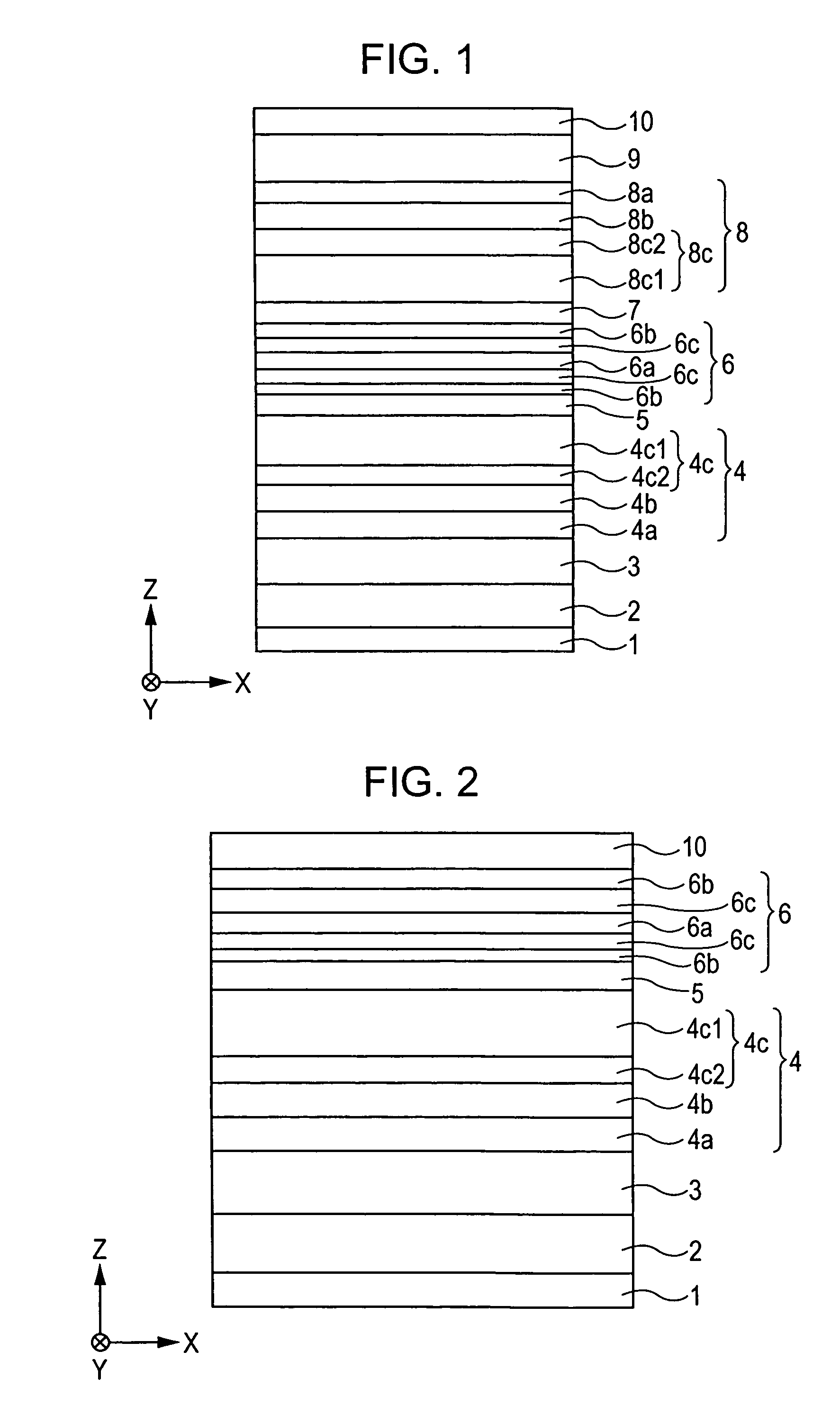
[0017]In the present aspect, since the above-described free magnetic layer has a laminated structure composed of the CoMnX alloy layer formed from a ternary alloy and the CoMnZ alloy layer likewise formed from a ternary alloy, the magnetostriction of the above-described free magnetic layer can be reduced.
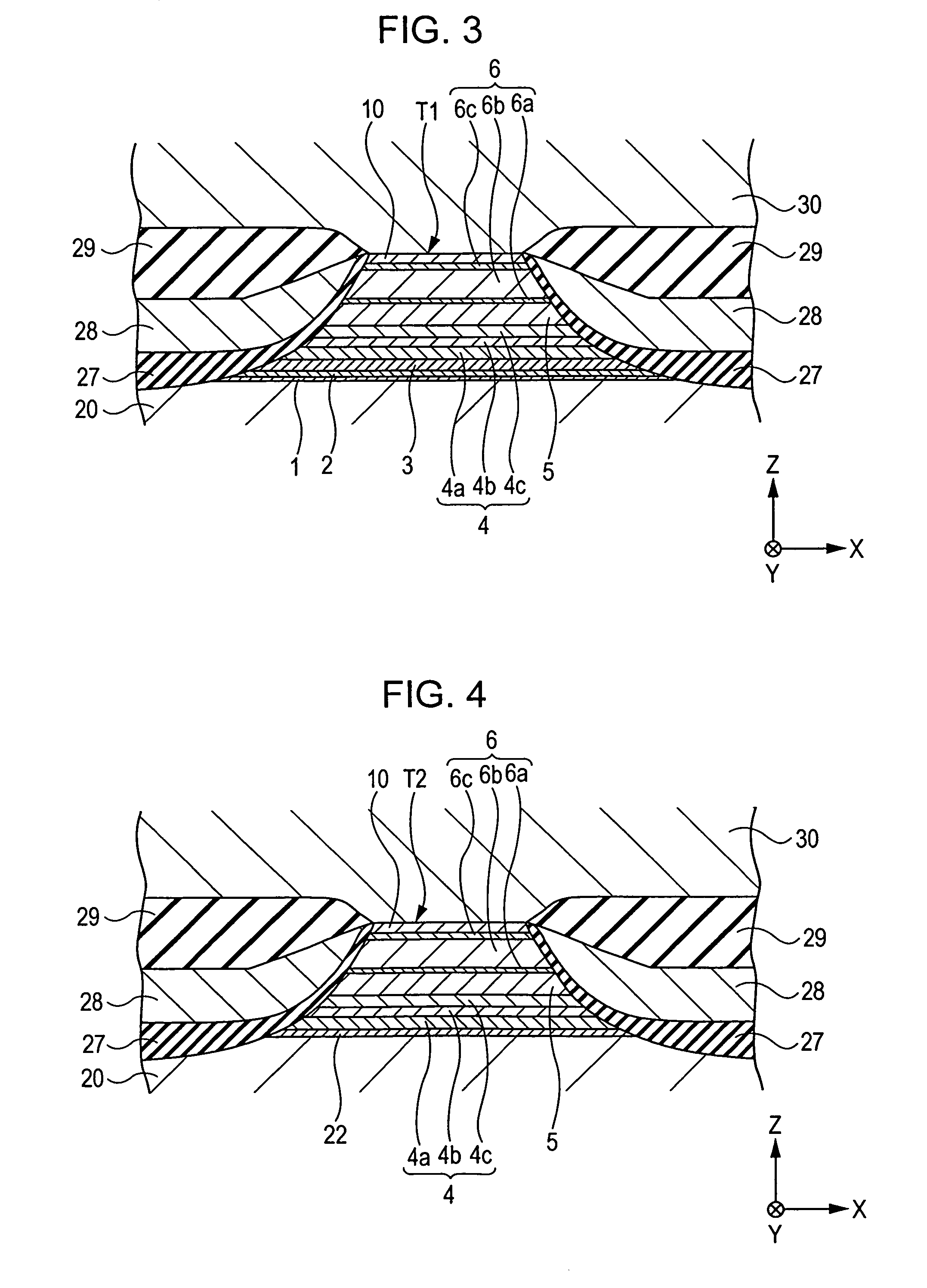
[0025]In particular, the present aspect of the invention can be effectively applied to the structure of a CPP type magnetic detection element, wherein a sense current is flowed in a direction perpendicular to the film surfaces of the above-described pinned magnetic layer, the non-magnetic material layer, and the free magnetic layer.
[0032]In the present aspect, since the above-described free magnetic layer has a laminated structure composed of the CoMnX alloy layer formed from a ternary alloy and the CoMnZ alloy layer likewise formed from a ternary alloy, the magnetostriction of the above-described free magnetic layer can be reduced.
[0033]In this manner, the magnetostriction of the free magnetic layer can be reduced while the ΔRA is maintained at a high value.

Problems solved by technology

Furthermore, on the grounds that, for example, noise is caused during the operation of a head, another problem occurs in that the magnetostriction of the above-described free magnetic layer must be reduced while a high ΔRA is maintained.

Method used


Image

  • Magnetic detection head and method for manufacturing the same
  • Magnetic detection head and method for manufacturing the same
  • Magnetic detection head and method for manufacturing the same

Examples


example 1

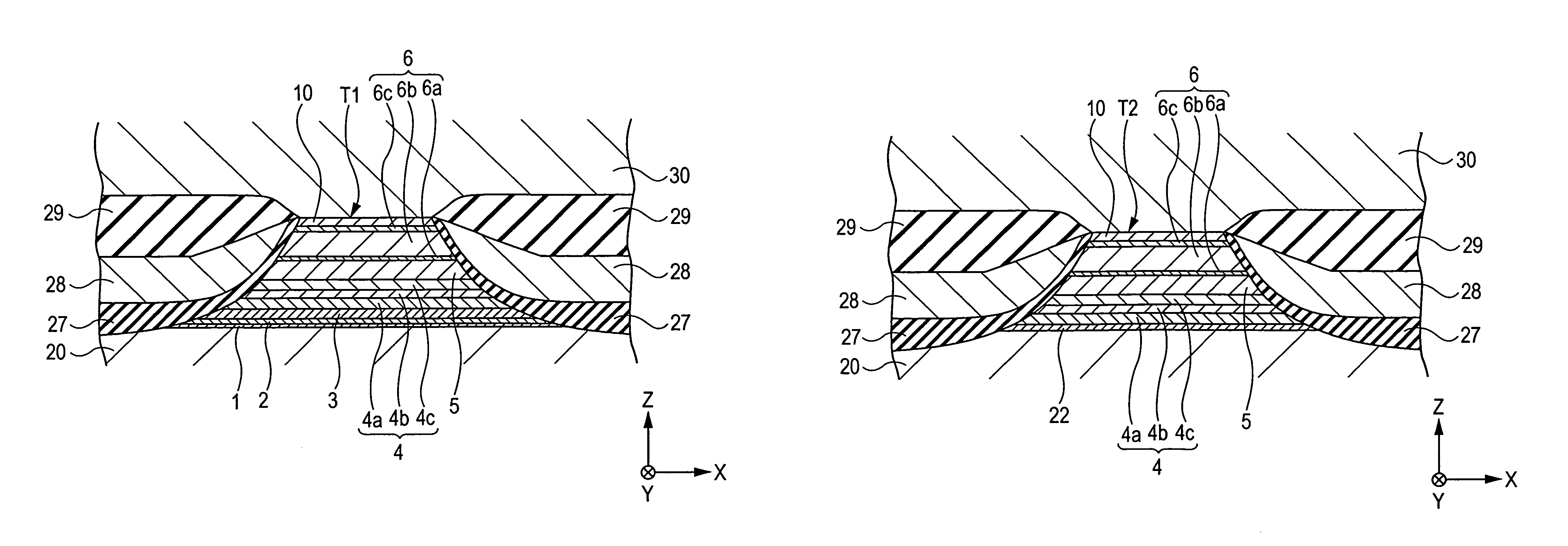
[0102][CoMnGe (9) / CoMnSn (5)]×7 / CoMnGe (10)

Sample

example 2

[0103][CoMnGe (16) / CoMnSn (5)]×4 / CoMnGe (16)

Sample

example 3

[0104]CoMnGe (10) / CoMnSn (80) / CoMnGe (10)

[0105]In the notation of the lamination configuration of the above-described free magnetic layer, a number in parentheses indicates a film thickness (angstrom), a term “×7” refers to that a film configuration in square brackets is laminated 7 times, and a term “×4” refers to that a film configuration in square brackets is laminated 4 times. For all samples, the compositional ratio of the element Co, the element Mn, and the element Ge in the CoMnGe alloy is 2:1:1, and the compositional ratio of the element Co, the element Mn, and the element Sn in the CoMnSn alloy is 2:1:1.

[0106]After each of the above-described samples were formed, each sample was subjected to a heat treatment.

[0107]The magnetostriction constant λs of the free magnetic layer of each sample was measured after the heat treatment, and the ΔRA of each sample was measured. The results thereof are shown in FIG. 6.

[0108]As is clear from FIG. 6, the magnetostriction constants λs of t...


PUM

PropertyMeasurementUnit
thicknessaaaaaaaaaa
thicknessaaaaaaaaaa
thicknessaaaaaaaaaa

Abstract

A magnetic detection element capable of maintaining the ΔRA at a high level and reducing the magnetostriction by improving a material for a free magnetic layer, as well as a method for manufacturing the same, is provided. The free magnetic layer includes a laminate composed of a CoMnX alloy layer formed from a metal compound represented by a compositional formula CoaMnbXc (where X represents at least one of Ge, Ga, In, Si, Pb, Zn, and Sb and a+b+c=100 atomic percent) and a CoMnZ alloy layer formed from a metal compound represented by a compositional formula CodMneZf (where Z represents at least one of Sn and Al and d+e+f=100 atomic percent). In this manner, the magnetostriction of the free magnetic layer can be reduced.

Description

BACKGROUND OF THE INVENTION[0001]1. Field of the Invention[0002]The present invention relates to a magnetic detection element including a pinned magnetic layer in which the magnetization direction is pinned and a free magnetic layer which is disposed on the above-described pinned magnetic layer with a non-magnetic material layer therebetween and in which the magnetization direction is varied due to an external magnetic field. In particular, it relates to a magnetic detection element capable of maintaining the product ΔRA of a variation of magnetoresistance ΔR and an element area A at a high level and reducing the magnetostriction of the free magnetic layer, as well as a method for manufacturing the same.[0003]2. Description of the Related Art[0004]FIG. 7 is a partial sectional view of a known magnetic detection element (spin-valve type thin film element) cut along a direction parallel to a surface facing a recording medium.[0005]In FIG. 7, reference numeral 1 denotes a substrate lay...

Claims


Application Information

Patent Timeline
Patent Type & Authority Patents(United States)
IPC IPC(8): G11B5/127
CPCB82Y40/00G01R33/093G11B5/3906H01L43/10H01F10/3281H01F41/302H01F10/3263H10N50/85
Inventor IDE, YOSUKESAITO, MASAMICHIISHIZONE, MASAHIKOHASEGAWA, NAOYA
Owner TDK CORPARATION
Learn More