Arrangement of a timing case cover

Active Publication Date: 2009-10-06
AUDI AG
View PDF8 Cites 4 Cited by
  • Summary
  • Abstract
  • Description
  • Claims
  • Application Information

AI Technical Summary

Benefits of technology

[0005]It is suggested that the sealing surface of the timing case cover or the timing case covers examined in a side view runs obliquely down to the inside, such that on the engine block-side a timing case chamber which decreases in its depth downward is formed. This yields a more weight-favorable engine block, facilitated installation of the control components such as the camshaft drive, differential shaft drive, oil pump drive, etc., by better accessibility, and adaptability of the timing case cover which may shorten the overall length of the internal combustion engine, which cover can be formed of a lightweight material such as magnesium or a plastic. Furthermore, within the timing case chamber and without an increase in the overall length of the internal combustion engine there can be housed therein other components of the engine such as an all separator for the crankcase ventilation means.
[0009]Furthermore an end wall section of the timing case cover which lies in the region of the through opening for the crankshaft and adjacent to the drive wheel of the accessory drive can be set back relative to an overlying end wall section. In this way, without added production engineering effort, the accessory drive for assemblies, for example for an air conditioning compressor and / or a generator, can be moved still closer to the internal combustion engine.
[0011]Furthermore, the engine block or the bed-plate construction can preferably border the timing case cover underneath its sealing surface and decoupled from the oil pan sealing surface. The problematic intersection of the sealing surfaces is thus avoided.

Problems solved by technology

In conventional, known internal combustion engines of generic design there is overlapping of the sealing surfaces of the oil pan—which seals to the bottom with the front-side timing case cover which seals to the front, which overlapping for internal combustion engines which are axially as short as possible can constitute a problematic seal.

Method used


Image

  • Arrangement of a timing case cover
  • Arrangement of a timing case cover
  • Arrangement of a timing case cover

Examples


Embodiment Construction

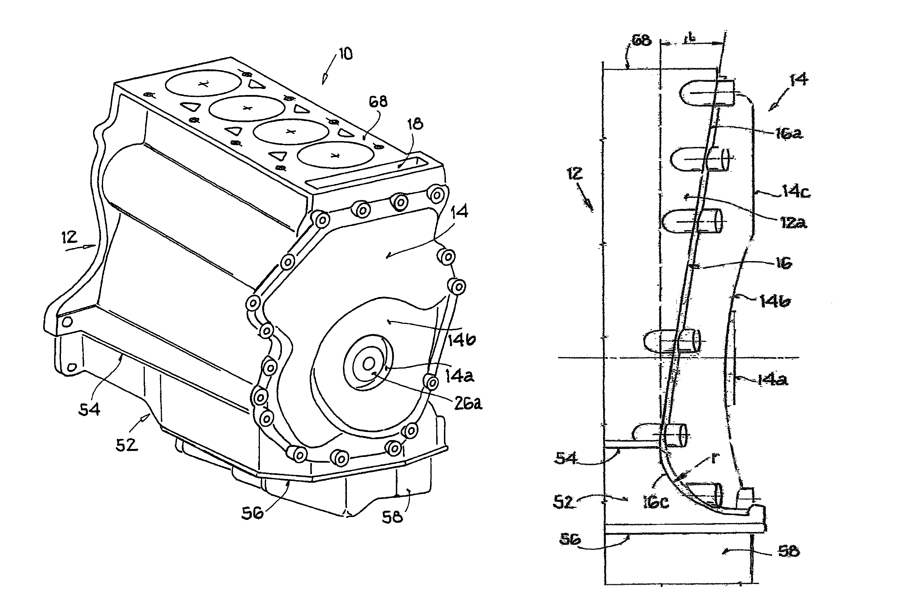
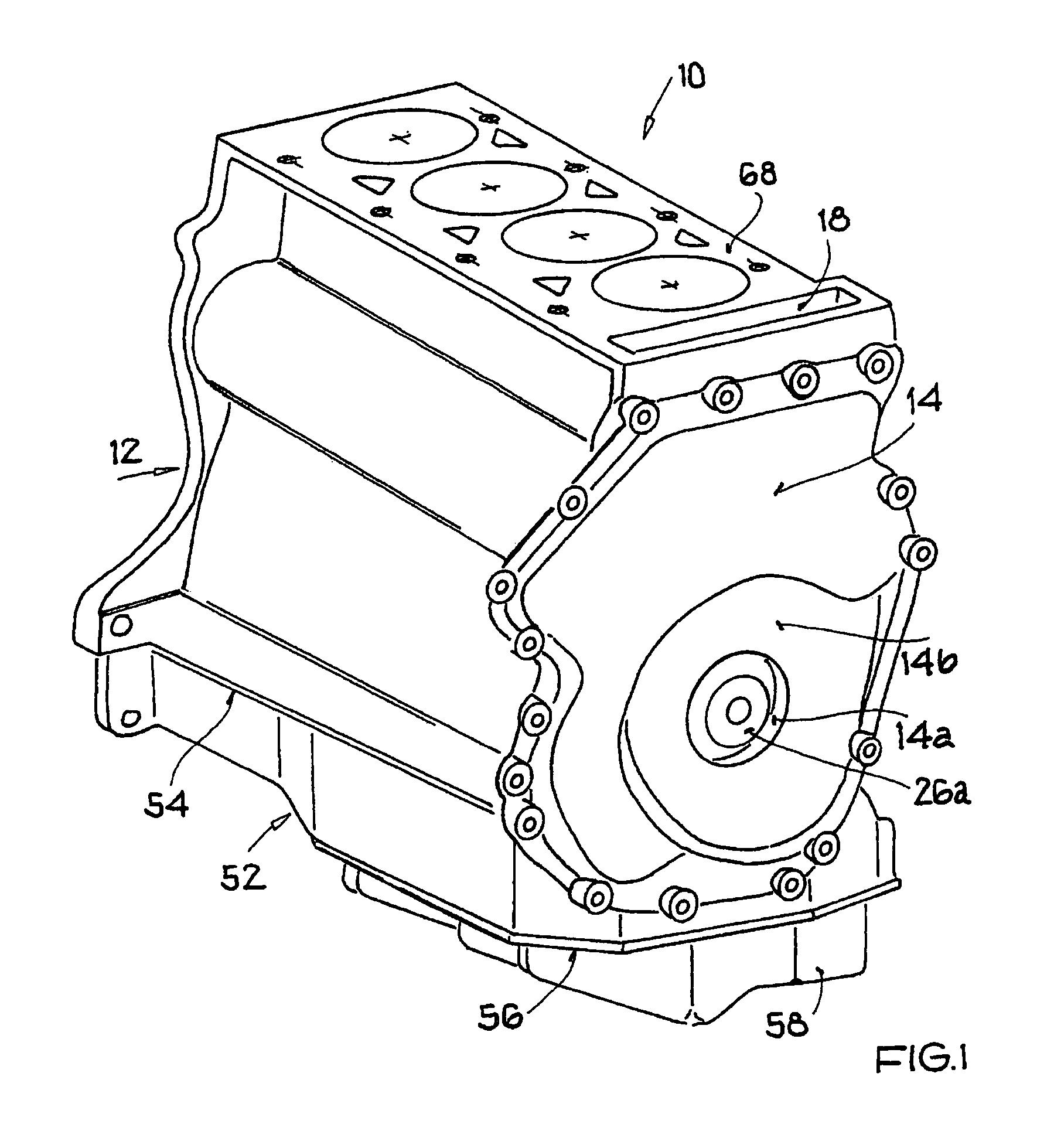
[0018]In FIG. 1 a four-cylinder, reciprocating piston, in-line internal combustion engine is designated as 10, but is shown without the cylinder head. The internal combustion engine 10 is only described to the extent this is necessary for an understanding of this invention. Otherwise the internal combustion engine 10 can be of known design familiar to one skilled in the art.

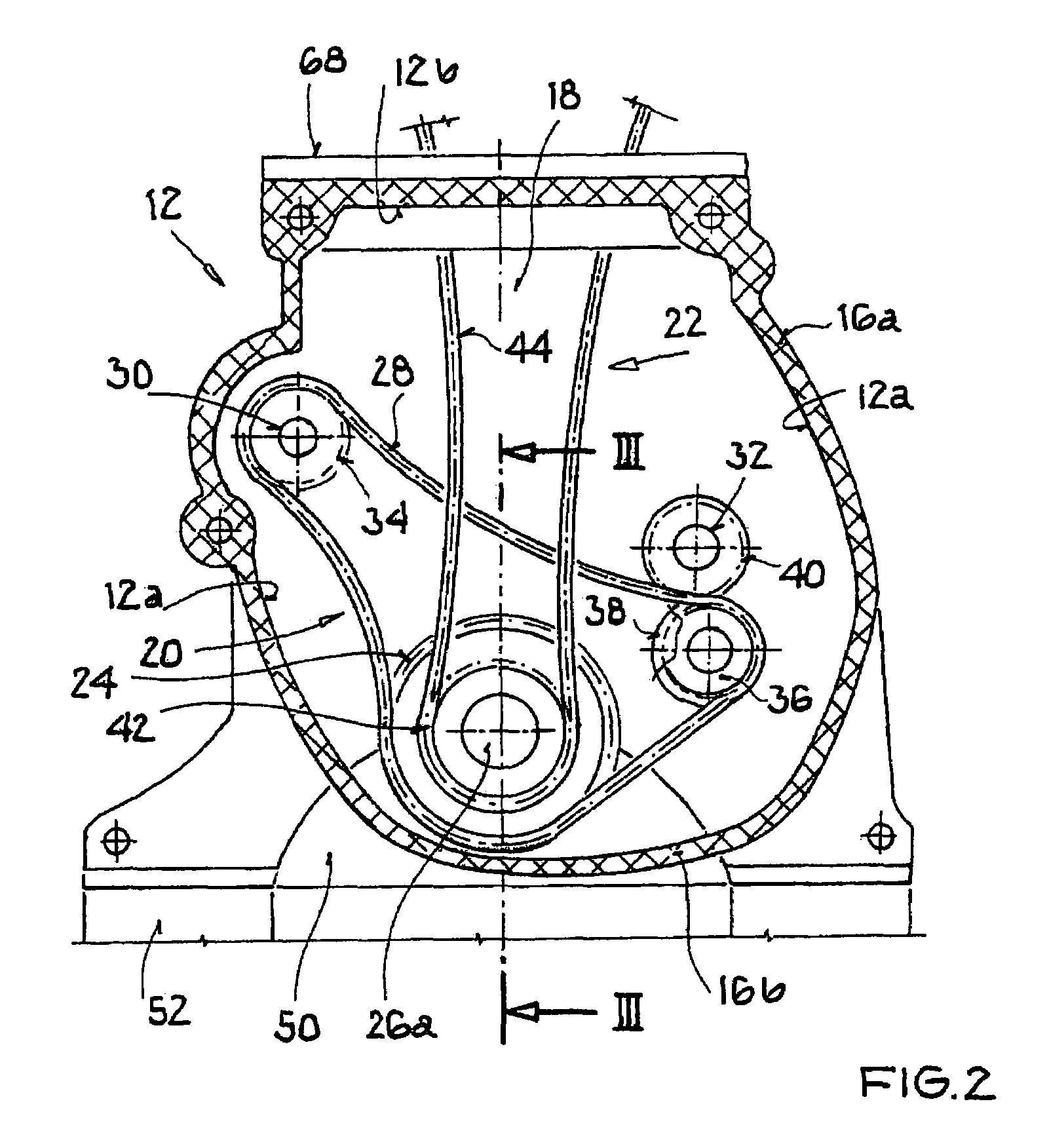
[0019]The engine block 12 (ZKG) of the internal combustion engine 10 produced in a diecasting process on its front (=control side) has a timing case cover 14 which is tightly connected to the engine block 12 by way of a more or less annular sealing surface 16 (compare FIG. 2, crosshatched) and optionally a seal (not shown) or is attached to the engine block by bolts which are not shown. The sealing surface 16 is made on the side walls 12a and on the upper terminating wall 12b of the engine block 12 and in the lower region on a bearing end plate 50 which is still to be described.

[0020]The timing case cover 14 encl...


PUM


Abstract

The invention relates to an arrangement of a timing case cover on a reciprocating-piston internal combustion engine, having an engine block (ZKG), a crankshaft pivot-mounted in the engine block, an oil pan which tightly seals the engine block to the bottom, and a timing case cover which is located on the engine block on the front side, which adjoins the engine block via a second, end-side sealing surface, and which has a through opening to rout out the drive torque of the crankshaft for an accessory drive. To achieve reliable sealing and a short structure of the internal combustion engine, the sealing surface of the timing case cover or timing case covers, examined in a side view, is made to run obliquely down to the inside such that on the engine block-side a timing case chamber which decreases in its depth downward is formed.

Description

[0001]This application is a U.S. National Phase under 35 USC § 371 of PCT / EP2005 / 016021, filed Oct. 1, 2005, which claims priority from DE 102004049030.9, filed Oct. 8, 2004, each of which is hereby incorporated by reference in its entirety.[0002]The invention relates to an arrangement of a timing case cover on a reciprocating piston internal combustion engine.BACKGROUND OF THE INVENTION[0003]In conventional, known internal combustion engines of generic design there is overlapping of the sealing surfaces of the oil pan—which seals to the bottom with the front-side timing case cover which seals to the front, which overlapping for internal combustion engines which are axially as short as possible can constitute a problematic seal.[0004]The object of the invention is to propose an arrangement of the generic type which in addition to reliable sealing of the oil pan and timing case cover permits a structure of the internal combustion engine which is favorable in terms of production engin...

Claims


Application Information

Patent Timeline
IPC IPC(8): F02B77/00F02F7/00F16P1/00
CPCF02F7/0046F02F7/0073Y10T74/2191
Inventor STEMMER, XAVER
Owner AUDI AG
Why Eureka
Try Eureka