Venting device

a venting device and valve technology, applied in the direction of valve operating means/releasing devices, gearing details, transportation and packaging, etc., can solve the problems of air out of the component along an unfavorable path, seals that wear at a faster rate, and available venting devices that have one or more limitations, etc., to achieve the effect of light weight and inexpensive manufacturing

Active Publication Date: 2009-10-06
FCA US
View PDF21 Cites 16 Cited by
  • Summary
  • Abstract
  • Description
  • Claims
  • Application Information

AI Technical Summary

Benefits of technology

[0005]It is an object of the present invention to provide a venting device that allows unrestricted intake and exhaust of air from a driveline component.
[0006]Another object of the present invention is to provide a venting device that prevents intake of water from an external environment to the driveline component.
[0007]Yet another object of the present invention is to provide a venting device that is light in weight, and is relatively inexpensive to manufacture.

Problems solved by technology

A positive pressure difference may force air out of the component along an unfavorable path, taking lubricant with it.
A negative pressure difference may cause water or other contamination to be drawn in through the component seals, or cause the seals to wear at a faster rate.
However, the available venting devices have one or more limitations.
The existing venting devices have a number of machined components, and therefore, they are expensive to manufacture.
The jiggle cap vents are usually short and can easily become clogged with mud.
In addition to these limitations, one or more of the existing venting devices do not allow the driveline components to breathe air freely.
The intake of water is not acceptable as it causes corrosion and contaminates the lubricant, reducing the life of the driveline components.

Method used


Image

  • Venting device
  • Venting device
  • Venting device

Examples


Embodiment Construction

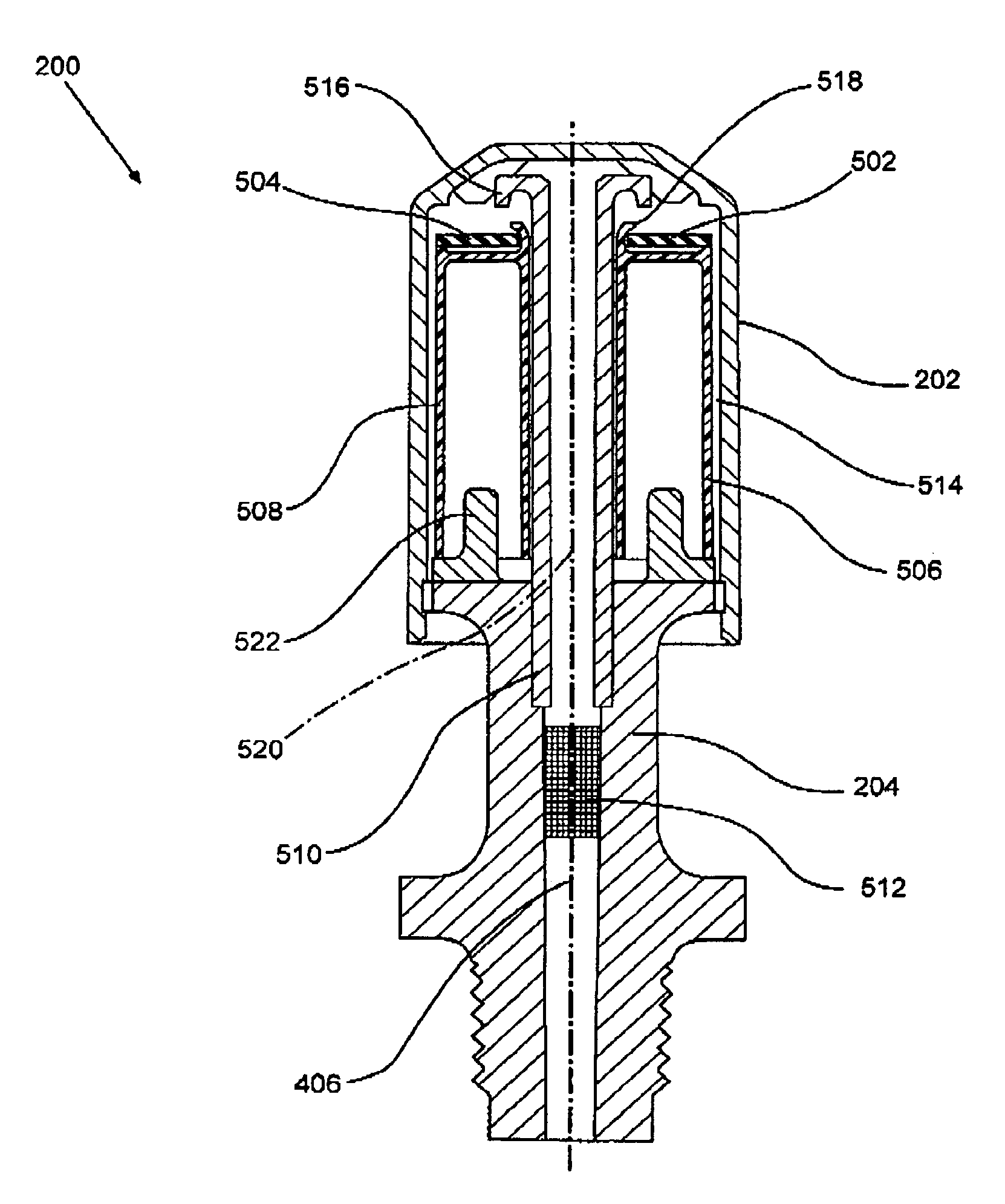
[0017]Various embodiments of the present invention describe a venting device. The venting device can be attached to a driveline component. The driveline component may be a front axle, a rear axle, a transmission, a transfer case, or similar component. The venting device includes one or more seals, one or more floats, and a cap. The one or more floats are coupled to the one or more seals. The one or more seals and the one or more floats are encapsulated by the cap. The venting device further includes a passage which allows intake and exhaust of air from the driveline component. The one or more floats are pushed by the water trying to enter the passage. This causes the one or more floats to move from a first position to a second position in the passage. At the second position, the one or more seals close the passage, thereby restricting intake of water into the driveline component.

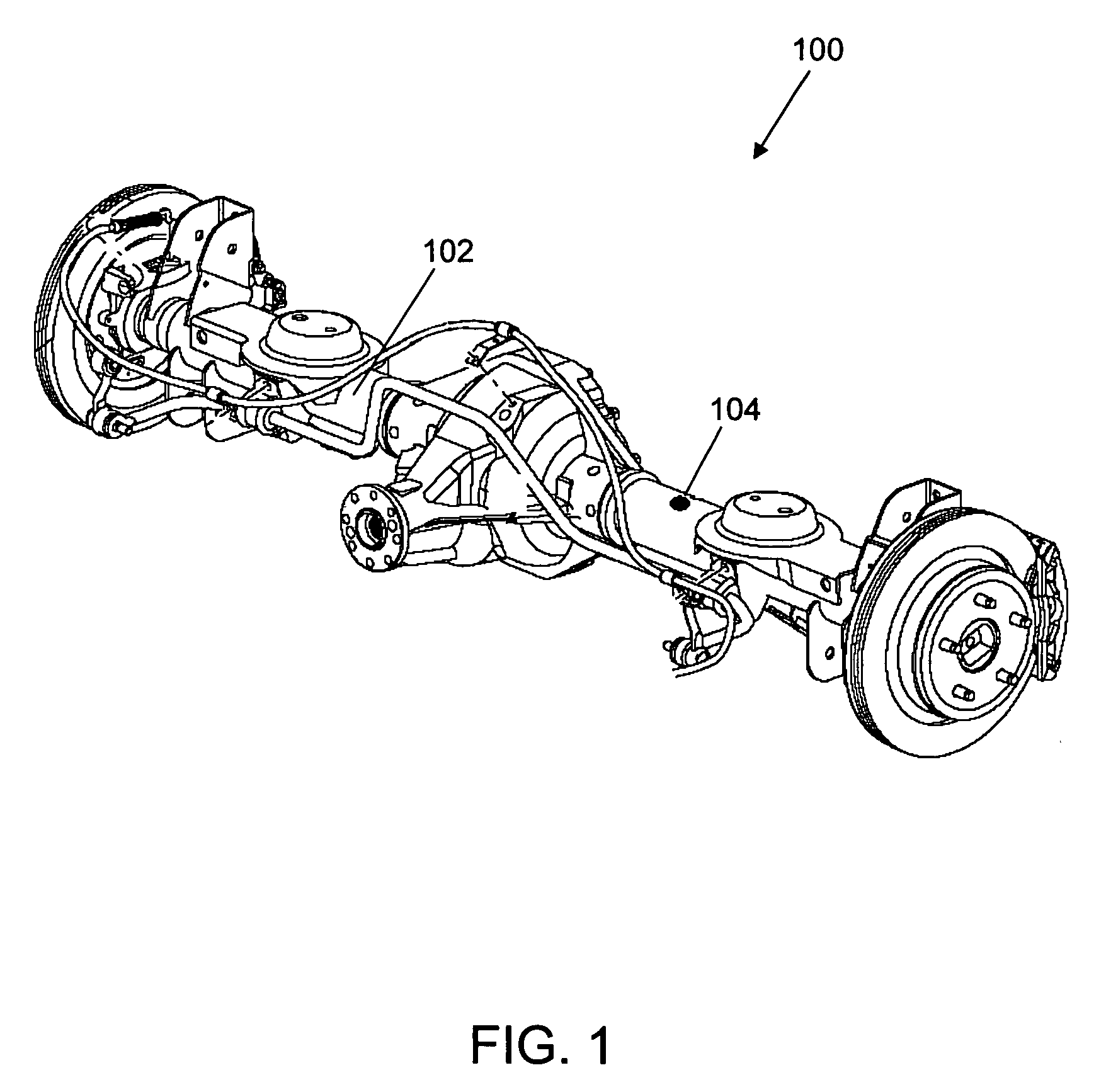
[0018]FIG. 1 is a view of an axle assembly 100, in accordance with various embodiments of the present inv...


PUM


Abstract

A venting device including one or more seals, one or more floats, and a cap is provided. The one or more seals and the one or more floats are encapsulated by the cap. The venting device further includes a passage, which allows intake and exhaust of air from a driveline component. The one or more floats are capable of moving from a first position to a second position in the passage. The one or more seals close the passage when the one or more floats are at the second position, thereby restricting intake of water in the driveline component.

Description

FIELD OF THE INVENTION[0001]The present invention generally relates to a driveline of a vehicle. More particularly, the present invention relates to a venting device for intake and exhaust of air from a driveline component.BACKGROUND OF THE INVENTION[0002]A vehicle's driveline component such as an axle, a transmission, a transfer case, or other component that transmits power from its engine for vehicular motion, gets heated during operation. As the component heats up, the air inside the component also heats and expands. Similarly, as the driveline component cools down, the air inside the component shrinks. Both of these situations produce a pressure difference between the air inside the driveline component and the ambient air, which must be relieved using a venting device. A positive pressure difference may force air out of the component along an unfavorable path, taking lubricant with it. A negative pressure difference may cause water or other contamination to be drawn in through t...

Claims


Application Information

Patent Timeline
Patent Type & Authority Patents(United States)
IPC IPC(8): F16K31/18
CPCF16K24/044Y10T74/2186Y10T137/7423Y10T137/7436
Inventor BUCKINGHAM, DAVID G.LAPPIN, THOMAS H.ELZIB, FAWAZ M.
Owner FCA US
Why Eureka
Try Eureka