Apparatus for converting ocean wave energy to electrical energy

a technology of electrical energy and apparatus, applied in the field of wave energy, can solve the problems of large cost and effort, complex structure, and large cost of electricity generation

Inactive Publication Date: 2007-12-20
MARILENA BURCIK
View PDF19 Cites 14 Cited by
  • Summary
  • Abstract
  • Description
  • Claims
  • Application Information

AI Technical Summary

Benefits of technology

[0031]A land based wave motion generator has a bore hole drilled into the bedrock at a coastline of an ocean. The bore hole has a lower end which communicates with the ocean underwater while the upper end is above water level, allowing wave motion within the bore hole. A wave race between the bore hole and the ocean may allow simple access of water pressure from waves to the water in the bore hole, or the wave race may actively concentrate the waves so as to produce a notably larger vertical rise and fall in the sea level within the bore hole.
[0054]a safety screen disposed near the open lower end of the bore hole, so as to prevent ingestion of objects from the body of water into the bore hole.
[0075]a safety screen disposed near the open lower end of the bore hole, so as to prevent ingestion of objects from the body of water into the bore hole.

Problems solved by technology

This distance is well within the practical distance for electricity transmission (electricity generation over long distances still suffers from some problems to this day).
Almost invariably, these schemes seek to provide large and complex structures in the tidal zone of the ocean, presumably at great cost and effort.
However, the locations most in need of wave energy generation facilities are not normally wealthy.
In addition, the requirements for complex mechanisms require that the equipment be imported from distant locations at further expense.
Worse, the necessity to import expensive equipment may make such installations impossible for regions which have unfavorable balances of trade.
One disadvantage of most of these schemes is that they require that large items of machinery work properly in the marine environment (under ocean water) for many cycles of use.
But the prior art schemes of putting equipment on the sea bed have disadvantages.
For example, the underwater environment is an extremely arduous environment in a number of ways.
Sea water, which contains various minerals and their salts, is corrosive by itself.
The ocean is continuously in motion, and particularly during storms, even the largest equipment can be destroyed by the enormous forces generated by masses of water in motion.
Sea life tends to grow onto and encrust any man-made object left under water for very long.
None of these devices teaches that the land itself may be a part of the power generation structure.
None of these devices teach equipment which may be manufactured on-site or in local areas lacking a “high tech” industrial base.
None teach pneumatic methods of transducing wave motion into electrical energy.
These devices are sophisticated, expensive, high maintenance apparatus, which require highly trained specialists to operate.

Method used


Image

  • Apparatus for converting ocean wave energy to electrical energy
  • Apparatus for converting ocean wave energy to electrical energy
  • Apparatus for converting ocean wave energy to electrical energy

Examples


second embodiment

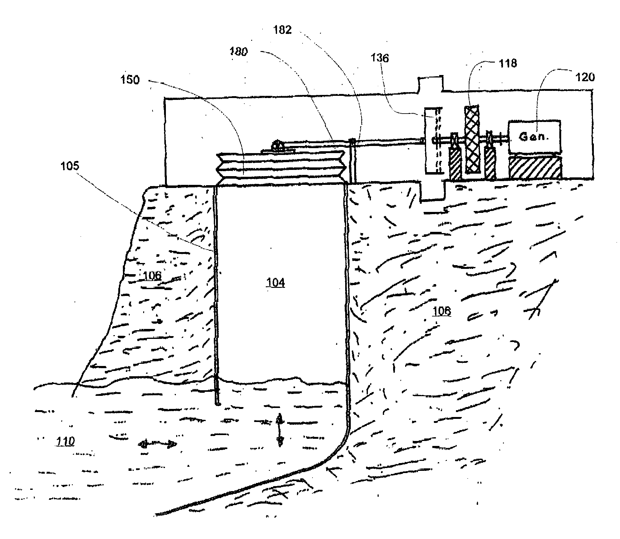
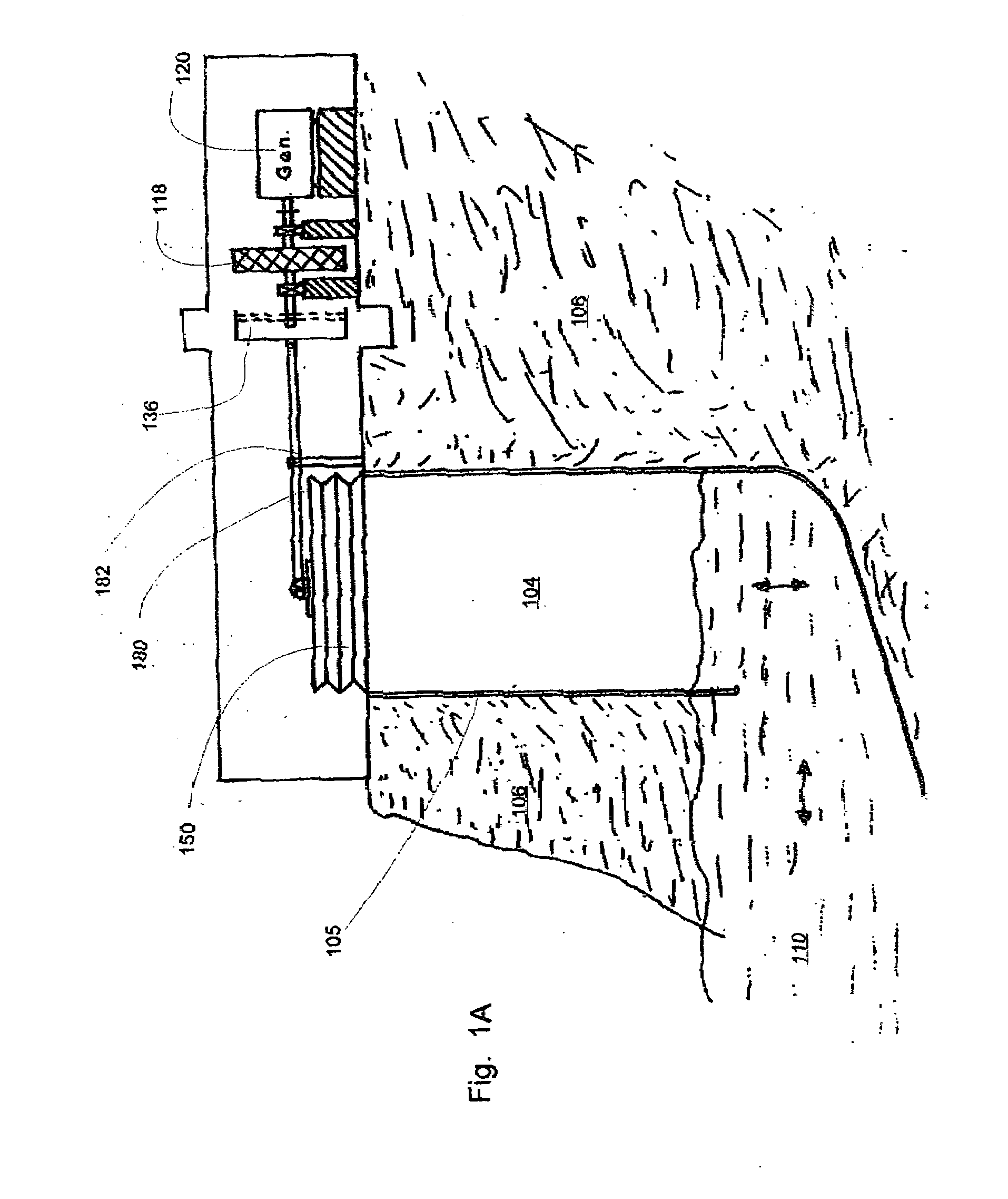
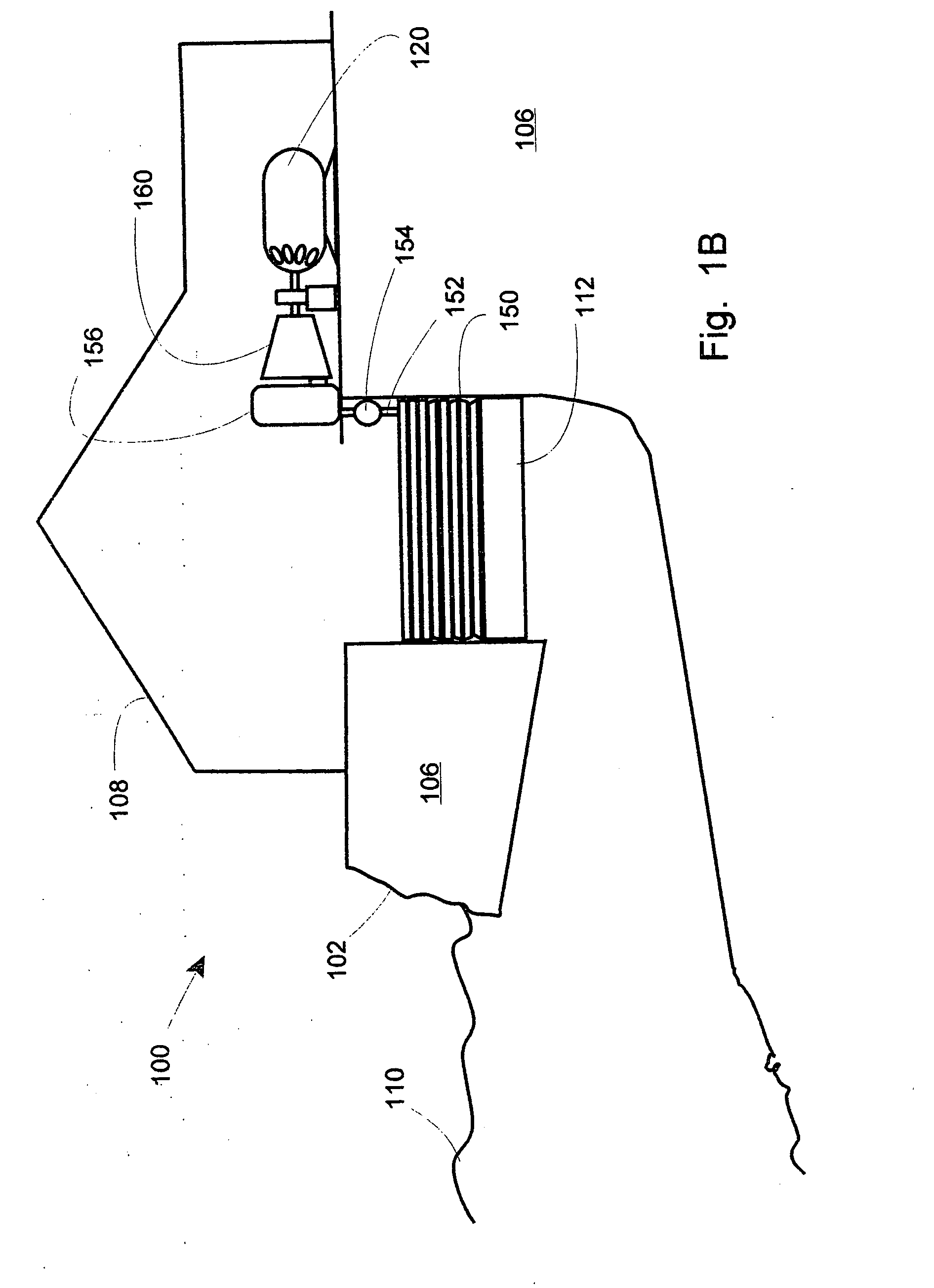
[0099]FIG. 1B is a partially cross-sectional side view of an alternative second embodiment of the invention using a bellows, air reservoir, and a turbine. Wave energy generator 100 is situated on coast 102 and has been provided with bore 104 by means of drilling, blasting, mining, construction or even backfilling and the creation of an artificial coast. Coast substrate 106 has shelter 108 (if necessary) atop it. Ocean / waves 110 may freely enter the bore 104 and thus raise and lower float piston 112 between first and second positions.

[0100]In this alternative embodiment, bellows 150 connects to air conduit 152 which may have valve 154 therein, and may connect to compressed air reservoir 156 which in turn feeds compressed air to turbine 160. In this embodiment, the flywheel may be omitted as the use of compressed air reservoir 156 may allow an even flow of air to the turbine and thus an even rotation of the shaft. Electrical generator 120 may also be a type which operates well despite...

third embodiment

[0105]FIG. 2 is a partially cross-sectional side view of an alternative “float” third embodiment of the invention using a ratchet and chain, and a flywheel.

[0106]Wave energy electricity generation facility 200 may be located on coastline 202 as previously described. Bedrock 206 may in some instances serve as an ideal substrate through which the bore is driven. Building 208, waves 210, reciprocal / rotary motion converter 236, and flywheel 218 as well as generator 220 may also be as previously discussed.

[0107]Bore spacer 232 having cross brace 234 may be used with this “float” embodiment to provide a filled in space within the bore. Reciprocal / rotary motion converter 236 may be part of the space 232 and may carry upon it the chain and sprocket mechanism of the converter discussed in reference to FIGS. 3A and 3B.

fourth embodiment

[0108]FIG. 4 is a partially cross-sectional side view of an alternative fourth embodiment of the invention using a ratcheted piston rod, elongated shaft, and flywheel. Wave energy facility 400 on coast 402 has bore 404 through substrate 406 covered by shelter 408.

[0109]Motions of large body of water 410 may move float 412 between two or more positions, which in turn moves rod 414, which may have a worm drive or cog drive to elongated shaft 416 bearing flywheel 418 and providing mechanical power to generator 420.

[0110]Such an elongated shaft 416 may be less preferable, due to weight, momentum and power restrictions.

[0111]Safety barrier 422 may be provided across the wave race or bore so as to prevent accidental or deliberate ingestion of human beings or wildlife into the mechanism. In embodiments, the bore diameter may be quite large.

[0112]Bore diameter 424 and throw 426 may vary considerably. Thus extremely small shafts and throws of inches in diameter / length may be used, while in o...


PUM


Abstract

A wave motion generator having a bore hole at a coastline of an ocean. The bore hole lower end communicates with the ocean underwater while the upper end is above water level, allowing wave motion within the bore hole. A float disposed within the bore hole may travel along the borehole between at least two positions. A linkage attached to the float converts the motion of the float to rotary motion of a generator shaft so as to induce electric current in the generator. The linkage may be pneumatic, in which the float motion induces pressurized air to drive a turbine, or it may be a chain drive, a shaft drive, etc.

Description

CROSS-REFERENCE TO RELATED APPLICATIONS[0001]The application claims the priority and benefit of copending U.S. Provisional Patent Application No. 60 / 784,555 filed Mar. 21, 2006 in the name of the same inventor, Frank Burcik and also entitled APPARATUS FOR CONVERTING OCEAN WAVE ENERGY TO ELECTRICAL ENERGY, the entire disclosure of which in incorporated herein by this reference.COPYRIGHT NOTICE[0002]A portion of the disclosure of this patent document contains material which is subject to copyright protection. The copyright owner has no objection to the facsimile reproduction by anyone of the patent document or the patent disclosure, as it appears in the Patent and Trademark Office patent file or records, but otherwise reserves all copyright rights whatsoever. 37 CFR 1.71(d).FIELD OF THE INVENTION[0003]This invention relates generally to wave energy and specifically to bore / float systems of generating energy from wave motion.STATEMENT REGARDING FEDERALLY FUNDED RESEARCH[0004]This inven...

Claims


Application Information

Patent Timeline
Patent Type & Authority Applications(United States)
IPC IPC(8): F03B13/12
CPCF03B13/1855F03B13/1875Y02E10/38F05B2260/4031F03B13/24Y02E10/30
Inventor BURCIK, FRANK
Owner MARILENA BURCIK
Why Eureka
Try Eureka