Engine inlet configuration

a technology for inlet ducts and engines, which is applied in the direction of machines/engines, mechanical equipment, transportation and packaging, etc., can solve the problems of inaccessible inlet duct installation points, difficult installation of ducts, and long length

Active Publication Date: 2015-10-15
SIKORSKY AIRCRAFT CORP
View PDF7 Cites 17 Cited by
  • Summary
  • Abstract
  • Description
  • Claims
  • Application Information

AI Technical Summary

Benefits of technology

[0006]Additionally or alternatively, in this or other embodiments the firewall has an airtight seal to the engine inlet radially outboard on the inlet duct via a flexible bellows seal to prevent ingestion of an engine compartment airflow into the engine inlet.
[0013]Additionally or alternatively, in this or other embodiments the firewall has an airtight seal to the engine inlet radially outboard on the inlet duct via a flexible bellows seal to prevent ingestion of an engine compartment airflow into the engine inlet.

Problems solved by technology

In some aircraft, however, the duct length is quite long making installation of the duct difficult due to manufacturing and assembly tolerance stackups between the engine front frame, the MRP and the inlet duct.
Further, in some configurations, the inlet duct installation points may be inaccessible.

Method used


Image

  • Engine inlet configuration
  • Engine inlet configuration
  • Engine inlet configuration

Examples


Embodiment Construction

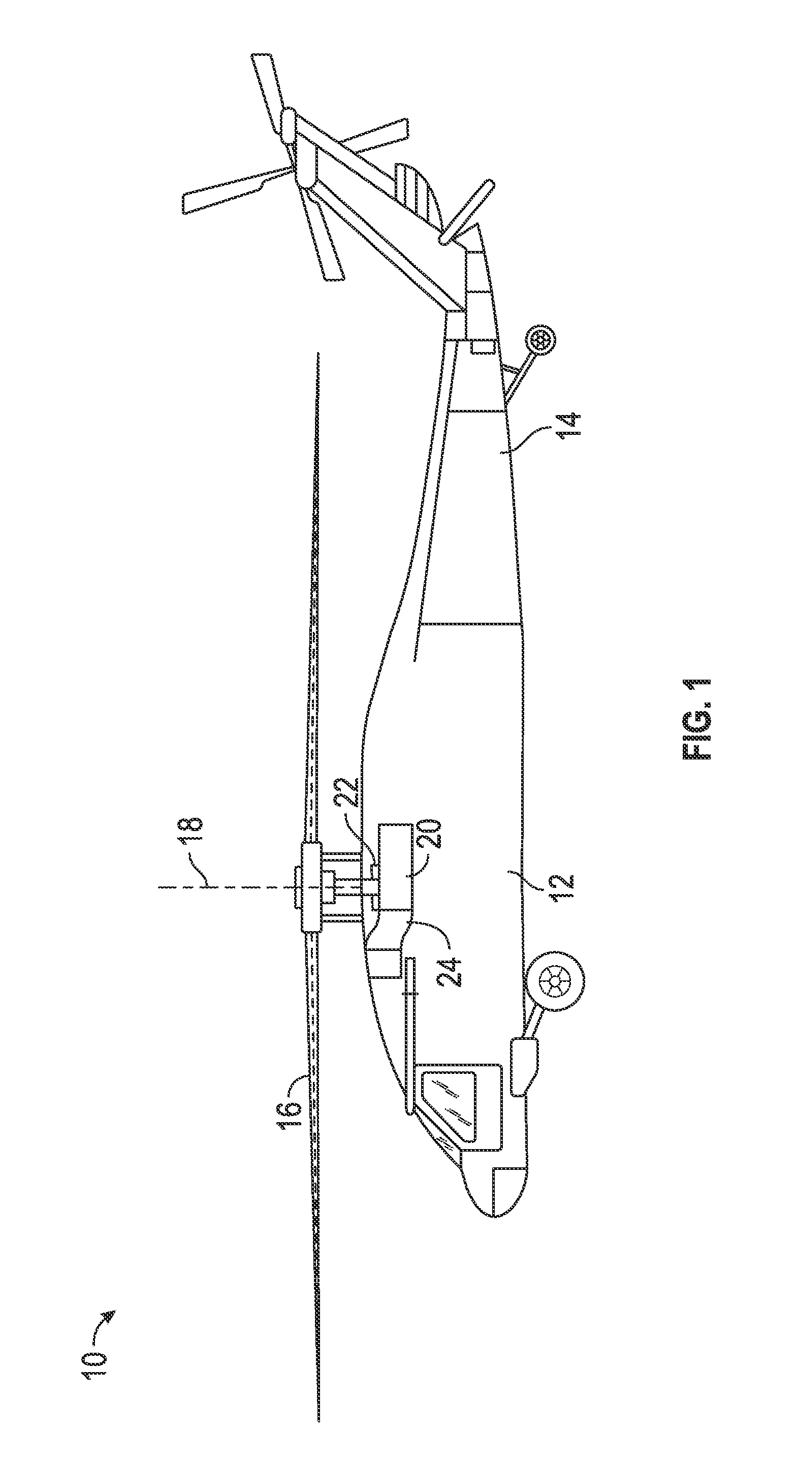
[0026]Shown in FIG. 1 is a schematic view of an embodiment of a rotary wing aircraft, in this embodiment a helicopter 10. The helicopter 10 includes an airframe 12 with an extending tail 14. A rotor assembly 16 is located at the airframe 12 and rotates about a main rotor axis 18. The main rotor assembly 16 is driven by an engine 20 via a gearbox 22. To supply airflow to the engine 20, an air inlet duct 24 is provided to direct the airflow to an engine inlet 26 (FIG. 4).

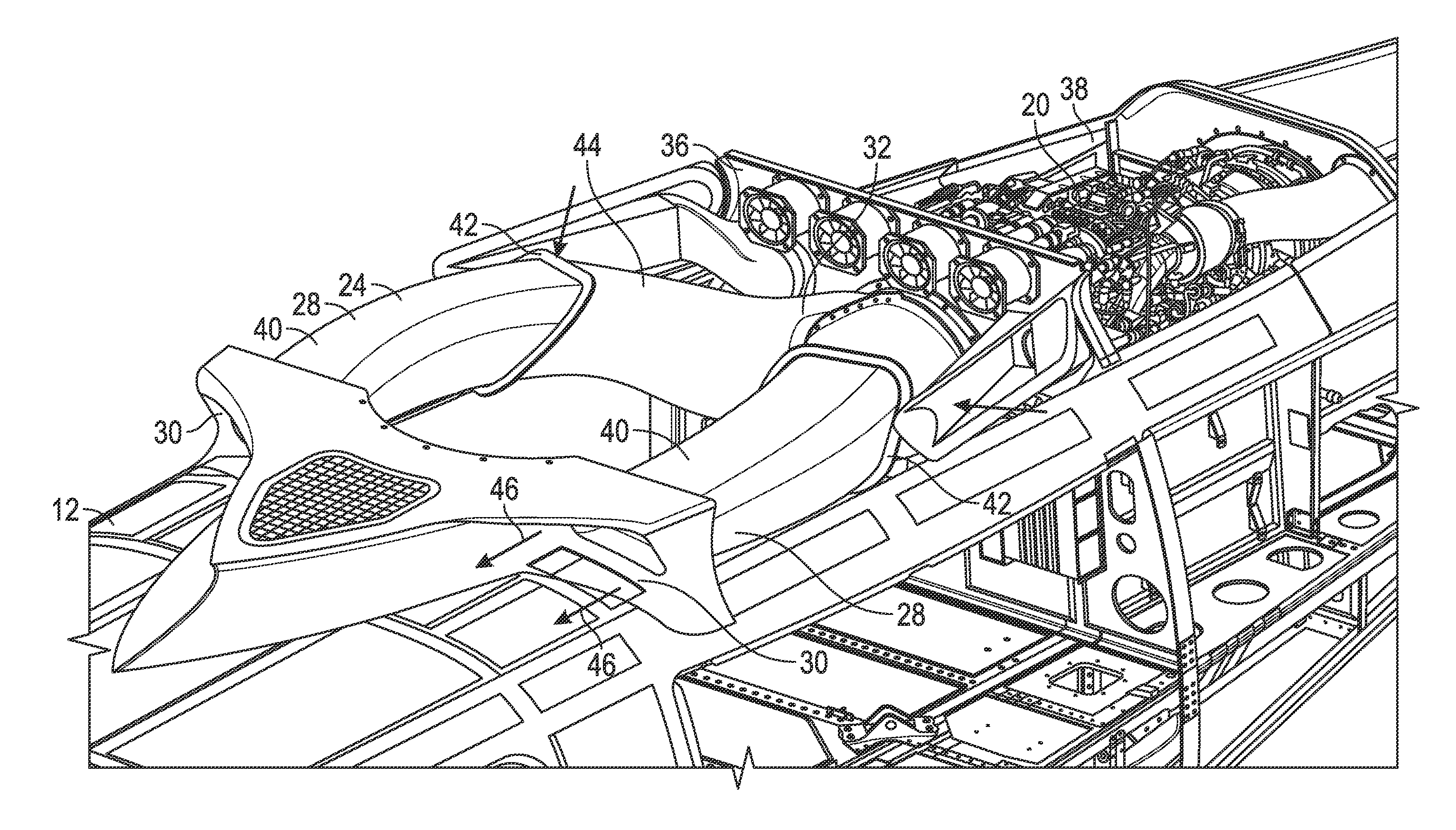
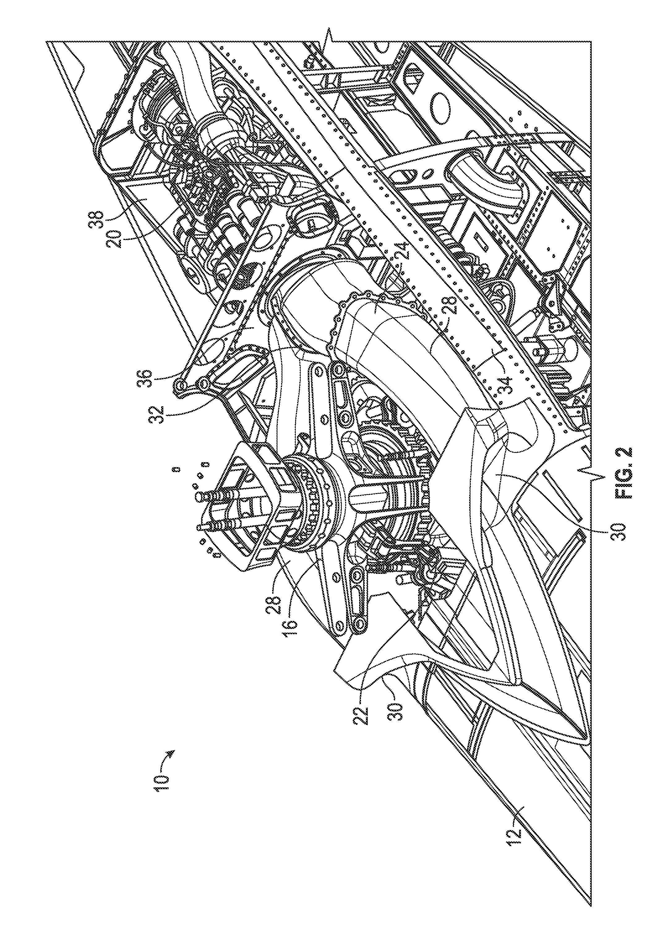
[0027]Referring to FIG. 2, the inlet duct 24 is bifurcated, with duct legs 28 each extending from an inlet opening 30 at each lateral side of the airframe 12 to a single duct outlet 32 at the engine 20. The inlet duct 24 extends through a portion of the airframe 12 referred to as a main rotor pylon (MRP) 34. The MRP 34 houses the gearbox 22 for the main rotor assembly 16, which is operably connected to the engine 20. The inlet duct 24 is bifurcated at least in part to route the inlet duct 24 around the gearbox 22 and ...


PUM


Abstract

An engine inlet assembly includes an inlet duct having a first inlet duct leg and a second inlet duct leg, the first inlet duct leg and the second inlet duct leg extending toward a common inlet duct outlet located at an engine inlet. The first inlet duct leg and the second inlet duct leg are fixedly secured to an airframe of an aircraft at an air inlet. The duct outlet has a floating interface with the engine inlet.

Description

BACKGROUND[0001]The subject matter disclosed herein relates to engine inlets, more specifically, to installation of engine inlet ducts and / or cowling.[0002]Engines for, for example, aircraft such as helicopters or other rotorcraft utilize engine inlet ducting to direct airflow into the compressor of the engine. Some systems, for example, single engine systems, utilize a bifurcated inlet duct, which takes two airflow streams and directs them to the compressor inlet. The duct extends from an inlet located at a portion of the airframe such as the main rotor pylon (MRP) and extends through the MRP and airframe to an engine inlet at the engine front frame. The duct is typically secured directly and rigidly to the engine front frame at the duct outlet, and secured to the inlet at the MRP. Secured at each end, the inlet duct is held rigidly in place.[0003]In some aircraft, however, the duct length is quite long making installation of the duct difficult due to manufacturing and assembly tol...

Claims


Application Information

Patent Timeline
Patent Type & Authority Applications(United States)
IPC IPC(8): B64D33/02B64C27/00
CPCB64D33/02B64D2033/0253B64C27/00B64D2033/0246
Inventor BOFILL, STEVENCHASEN, SCOTT A.SIMONETTI, JOSEPH LAWRENCELAMB, JR., DONALD WILLIAM
Owner SIKORSKY AIRCRAFT CORP
Why Eureka
Try Eureka