Gear box for hydraulic energy recovery

a hydraulic energy recovery and gear box technology, applied in the direction of fluid gearings, gearings, road transportation, etc., can solve the problems of limiting the ability to optimally control engine speed and pump displacement, needing to stop the vehicle, and many of the previously disclosed systems do not lend themselves to us

Inactive Publication Date: 2009-10-06
PARKER HANNIFIN CORP
View PDF71 Cites 70 Cited by
  • Summary
  • Abstract
  • Description
  • Claims
  • Application Information

AI Technical Summary

Benefits of technology

[0013]According to a further aspect of the invention, provision is made for continued hydraulic braking even when the energy storage device cannot accept any more energy. This is accomplished by directing flow from one or more hydraulic motors that are being reversely driven as pumps to through a pressure relief valve so that the hydraulic system will continue to absorb energy and thereby continue to effect vehicle braking of the vehicle when braking is still be commanded.

Problems solved by technology

Many of the previously disclosed systems do not lend themselves to use in existing truck designs whereas others require specially fabricated hydrostatic drive components.
A problem with some hydrostatic transmissions has been the need to stop the vehicle to shift between different gear ratios.
The transmission disclosed in this patent, however, limits the ability to optimally control engine speed and pump displacement independently of existing driving conditions, nor does such transmission lend itself to efficient operation at “on highway” speeds, typically speeds greater than 40 mph.

Method used


Image

  • Gear box for hydraulic energy recovery
  • Gear box for hydraulic energy recovery
  • Gear box for hydraulic energy recovery

Examples


Embodiment Construction

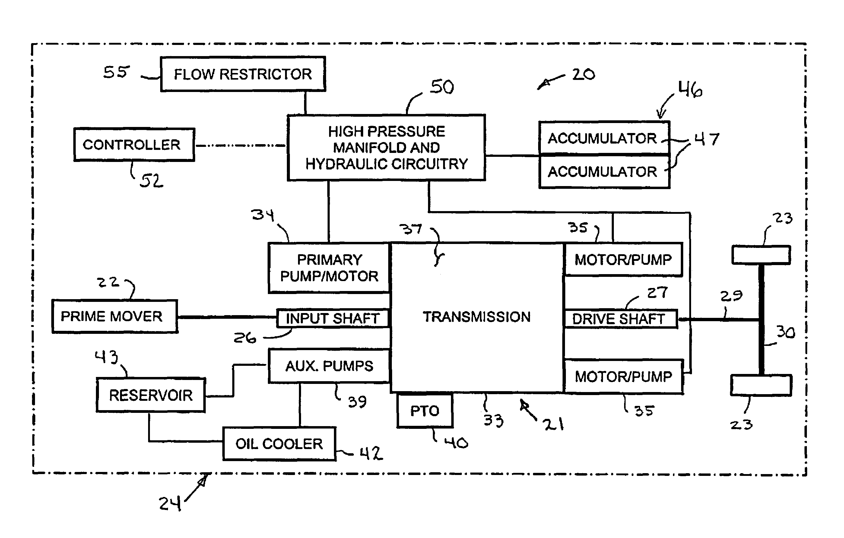
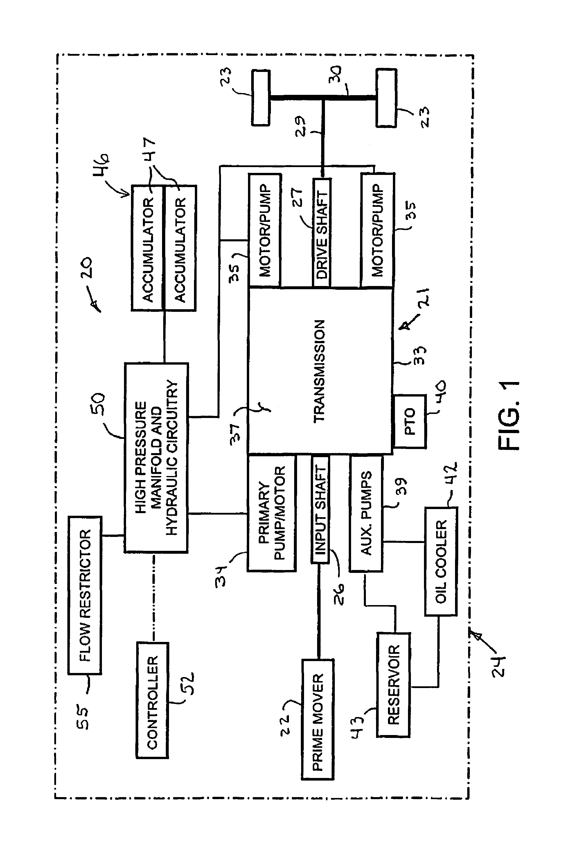
[0035]Referring now in detail to the drawings and initially to FIG. 1, an exemplary vehicle drive system according to the present invention is indicated generally by reference numeral 20. The vehicle drive system 20 includes a power drive unit 21 connected between a prime mover 22 and the drive wheel or wheels 23 of a vehicle generally denoted by reference numeral 24. The prime mover preferably is an internal combustion (IC) engine, but other prime movers could also be used, such as gas turbines, electric motors and fuel cells. The power drive unit includes a power input shaft 26 to which the engine is drivingly connected by any suitable means and an output drive shaft 27 drivingly connected to one or more the wheels 23 of the vehicle by any suitable means, such as by a drive shaft 29 and transaxle 30.

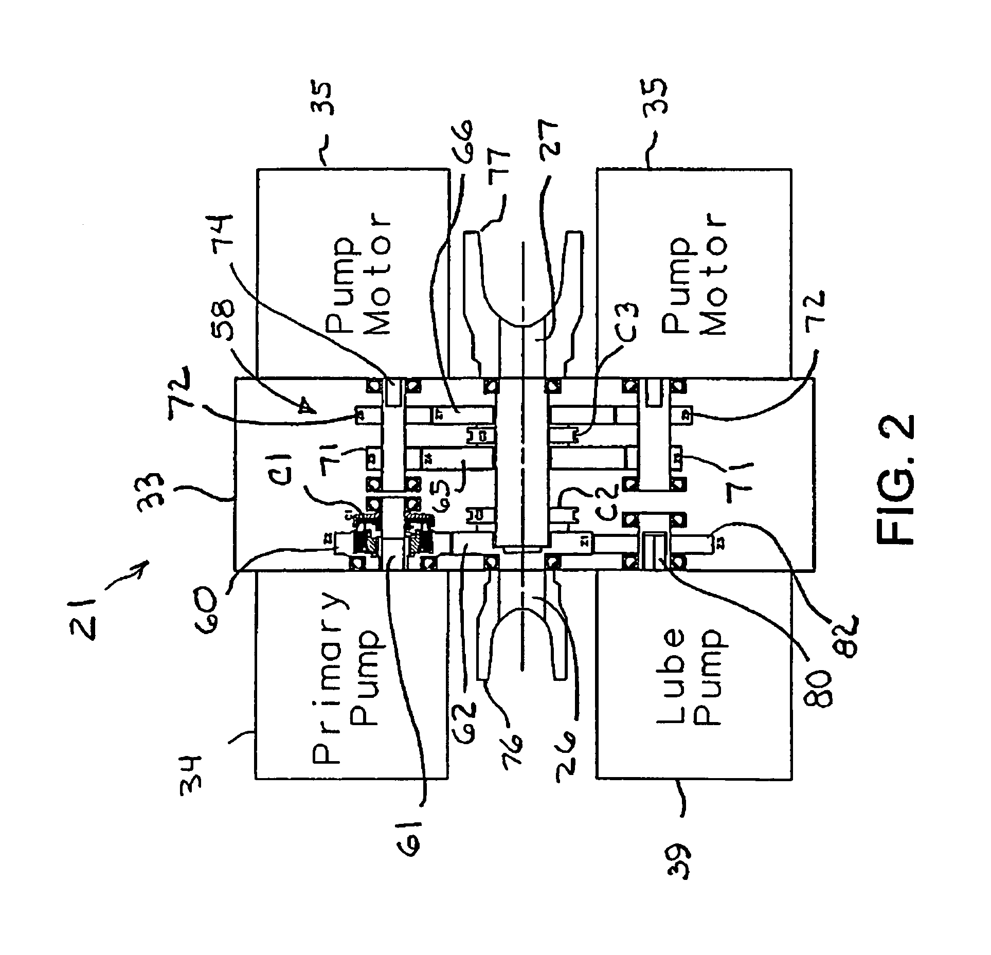
[0036]The power drive unit 21 is characterized by a housing 33 that provides a mount for one or more primary hydraulic pumps 34 and one or more hydraulic drive motors 35 (two being sho...


PUM


Abstract

A hydraulic energy recovery and a mechanical drive system in one unit that also provides integral mounting of hydraulic pump/motors for primary drive, secondary drive, and pumps for cooling, lubrication, and low pressure systems along with a mounting position for a power take-off device.

Description

RELATED APPLICATIONS[0001]This application claims the benefit of U.S. Provisional Application No. 60 / 674,031 filed Apr. 22, 2005, U.S. Provisional Application No. 60 / 764,908 filed Feb. 3, 2006, and U.S. Provisional Application No. 60 / 775,105 filed Feb. 21, 2006, all of which are hereby incorporated by reference in their entireties.FIELD OF THE INVENTION[0002]This invention relates generally to a unitized vehicle drive system that provides both hydraulic energy storage and recovery along with a direct mechanical drive mode for maximum fuel consumption efficiency throughout the vehicle's duty cycle. The drive system can be used on a variety of vehicle types, including in particular garbage collection vehicles and other vehicles that make frequent starts and stops, and which at least part of the time need to travel at “on-highway” speeds.BACKGROUND OF THE INVENTION[0003]For many years there has been recognition that vehicles could be made more fuel-efficient if the energy normally lost...

Claims


Application Information

Patent Timeline
Patent Type & Authority Patents(United States)
IPC IPC(8): B60K17/356
CPCF16H47/02Y02T10/76F16H2047/025
Inventor KOVACH, JOSEPH A.BLALOCK, JAMES H.RINK, STEVEN C.TURNER, STACY H.ZHANG, HAO
Owner PARKER HANNIFIN CORP
Why Eureka
Try Eureka