Method and/or apparatus for cross-color and cross-luminance suppression using shimmer detection

a technology of shimmer detection and detection method, applied in the field of video processing, can solve the problems of yc-interference noise, cross-color and cross-luminance, motion detectors that incorrectly label still areas as motion areas, etc., and achieve the effect of removing yc-interference nois

Inactive Publication Date: 2009-10-06
AVAGO TECH WIRELESS IP SINGAPORE PTE
View PDF5 Cites 0 Cited by
  • Summary
  • Abstract
  • Description
  • Claims
  • Application Information

AI Technical Summary

Benefits of technology

[0015]The objects, features, and advantages of the present invention include providing a method and / or apparatus of removing YC-interference noise from post-separation video signals that (i) does not reduce the vertical or horizontal resolution of the video, (ii) filters only those pixel locations affected by noise without causing artifacts in the presence of motion and / or (iii) is effective in the presence of strong YC-interference noise.

Problems solved by technology

Some mixing of the two signals is unavoidable, resulting in YC-interference noise, also called cross-color and cross-luminance.
Because non-adaptive temporal filtering causes visual artifacts in moving areas of the video, some method of adapting the filter to prevent those artifacts is needed.
The problem with such an approach is that the YC-interference noise that the filter is trying to eliminate can cause motion detectors to incorrectly label still areas as motion areas.

Method used


Image

  • Method and/or apparatus for cross-color and cross-luminance suppression using shimmer detection
  • Method and/or apparatus for cross-color and cross-luminance suppression using shimmer detection
  • Method and/or apparatus for cross-color and cross-luminance suppression using shimmer detection

Examples


Embodiment Construction

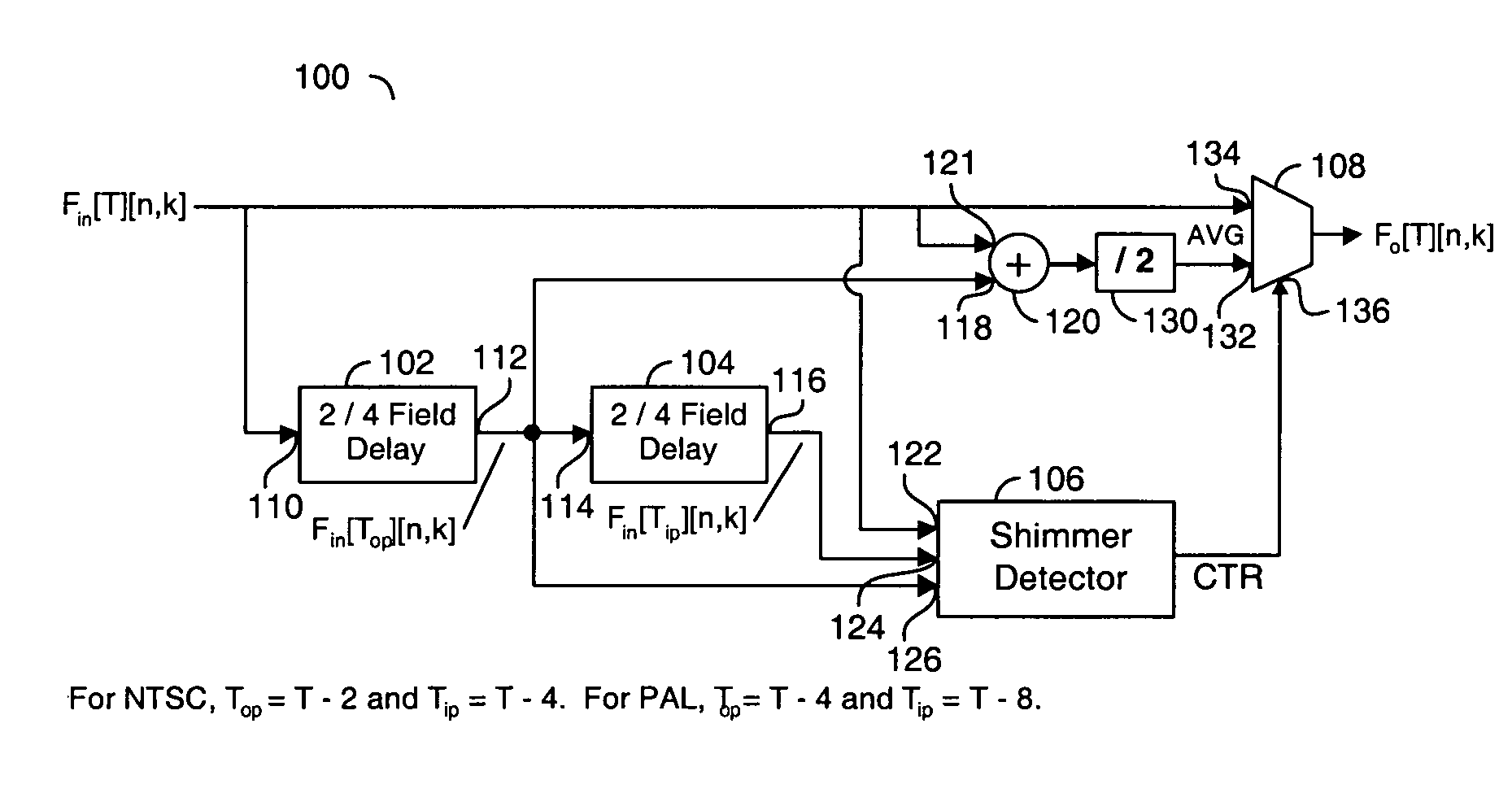
[0026]Referring to FIG. 6, a block diagram of a circuit 100 is shown in accordance with a preferred embodiment of the present invention. The circuit 100 generally comprises a block (or circuit) 102, a block (or circuit) 104, a block (or circuit) 106 and a block (or circuit) 108. The circuit 102 may be implemented as a delay circuit. In one example, the circuit 102 may be implemented as a 2 / 4 field delay circuit. Similarly, the circuit 104 may be implemented as a delay circuit. In one example, the circuit 104 may be implemented as a 2 / 4 field delay circuit. The circuit 106 may be implemented as a detector circuit. In one example, the circuit 106 may be implemented as a shimmer detector circuit. The circuit 108 may be implemented as a multiplexer circuit. The circuit 102 may have an input 110 that receives an input signal. The circuit 102 may have an output 112 that presents a signal to an input 114 of the circuit 104. The circuit 104 may have an output 116. The output 112 may also be...


PUM


Abstract

An apparatus comprising one or more delay circuits, a shimmer detector circuit, an averaging circuit, and a multiplexer. The delay circuits may be configured to have a delay of one or more frame periods based on the format of the input video signal. The shimmer detector circuit may be configured to (i) determine which pixel locations in the input video signal exhibit the YC-interference noise oscillation pattern based on the input signal and the output of the delay circuits and (ii) generate a control signal in response to the output of the delays circuits and the input signal. The averaging circuit may be configured to calculate an average of the input signal and the output of the first delay circuit. The multiplexer may be configured to present (i) the input signal when the control signal is in a first state and (ii) the average signal when the control signal is in a second state.

Description

[0001]This application claims the benefit of U.S. Provisional Application No. 60 / 740,860, filed Nov. 30, 2005 and is hereby incorporated by reference in its entirety.FIELD OF THE INVENTION[0002]The present invention relates to video processing generally and, more particularly, to a method and / or apparatus for cross-color and cross-luminance suppression using shimmer detection.BACKGROUND OF THE INVENTION[0003]In composite video signals, the luminance and chrominance signals are transmitted in the same bandwidth. The chrominance signal is modulated onto a sub-carrier signal and then added to a luminance signal to create a baseband signal. The baseband signal is then modulated onto a carrier for transmission. At the decoder, the baseband signal must be processed to separate the chrominance and luminance signals. Some mixing of the two signals is unavoidable, resulting in YC-interference noise, also called cross-color and cross-luminance. Cross-color is the result of decoding part of th...

Claims


Application Information

Patent Timeline
Patent Type & Authority Patents(United States)
IPC IPC(8): H04N11/14
CPCH04N9/646
Inventor STANTON, MARK E.
Owner AVAGO TECH WIRELESS IP SINGAPORE PTE
Why Eureka
Try Eureka