System and method for distributed input distributed output wireless communications

a wireless communication and distributed input technology, applied in the field of communication systems, can solve the problems of reducing affecting the performance of the mimo system, and rapidly deteriorating efficiency

Active Publication Date: 2009-10-06
REARDEN LLC
View PDF50 Cites 327 Cited by
  • Summary
  • Abstract
  • Description
  • Claims
  • Application Information

AI Technical Summary

Problems solved by technology

1. Physical limitations: MIMO antennas on a given device must have sufficient separation between them so that each receives a statistically independent signal. Although MIMO throughput improvements can be seen with antenna spacing of even fractions of the wavelength,
the efficiency rapidly deteriorates as the antennas get closer, resulting in lower MIMO throughput multipliers.
Also, for small antenna spacing, mutual coupling effects may degrade the performance of MIMO systems.
Moreover, as the antennas are crowded together, the antennas typically must be made smaller, which can impact the antenna efficiency as well.
Finally, with lower frequencies and longer wavelengths, the physical size of a single MIMO device can become unmanageable.
Each MIMO receiver / transmitter subsystem produces a certain level of noise.
As more and more of these subsystems are placed in close proximity to each other, the noise floor increases.
3. Cost and power limitations.
Although there are MIMO applications where cost and power consumption are not an issue, in a typical wireless product, both cost and power consumption are critical constraints in developing a successful product.
Unlike many aspects of digital systems which scale with Moore's Law (an empirical observation, made by Intel co-founder Gordon Moore, that the number of transistors on an integrated circuit for minimum component cost doubles about every 24 months; source: http: / / www.intel.com / technology / mooreslaw / ), such analog-intensive subsystems typically have certain physical structural size and power requirements, and scale in cost and power linearly.
So, a many-antenna MIMO device would become prohibitively expensive and power consumptive compared to a single-antenna device.
Up to 10 antenna MIMO systems have been contemplated (particularly at higher microwave frequencies due to shorter wavelengths and closer antenna spacing), but much beyond that is impractical except for very specialized and cost-insensitive applications.
In practice, however, such a system is extremely difficult to implement and of limited utility.
For one thing, there are now a minimum of two distinct communications paths per device that must be maintained to achieve improved throughput, with the second relaying link often of uncertain availability.
Also, the devices are more expensive, physically larger, and consume more power since they have at a minimum a second communications subsystem and greater computational needs.
Finally, as the simultaneous channel utilization (e.g. the simultaneous phone call transmissions utilizing MIMO techniques) grows, the computational burden for each device grows (potentially exponentially as channel utilization increases linearly), which may very well be impractical for portable devices with tight power and size constraints.

Method used


Image

  • System and method for distributed input distributed output wireless communications
  • System and method for distributed input distributed output wireless communications
  • System and method for distributed input distributed output wireless communications

Examples


Embodiment Construction

[0089]In the following description, for the purposes of explanation, numerous specific details are set forth in order to provide a thorough understanding of the present invention. It will be apparent, however, to one skilled in the art that the present invention may be practiced without some of these specific details. In other instances, well-known structures and devices are shown in block diagram form to avoid obscuring the underlying principles of the invention.

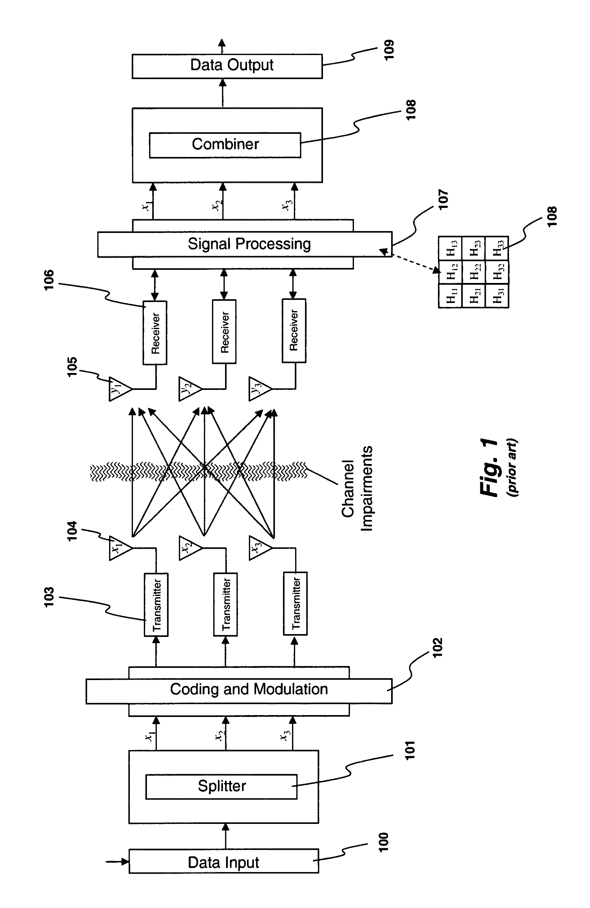
[0090]FIG. 1 shows a prior art MIMO system with transmit antennas 104 and receive antennas 105. Such a system can achieve up to 3× the throughput that would normally be achievable in the available channel. There are a number of different approaches in which to implement the details of such a MIMO system which are described in published literature on the subject, and the following explanation describes one such approach.

[0091]Before data is transmitted in the MIMO system of FIG. 1, the channel is “characterized.” This is acc...


PUM


Abstract

A system and method are described for compensating for frequency and phase offsets in a multiple antenna system (MAS) with multi-user (MU) transmissions (“MU-MAS”). For example, a method according to one embodiment of the invention comprises: transmitting a training signal from each antenna of a base station to one or each of a plurality of wireless client devices, one or each of the client devices analyzing each training signal to generate frequency offset compensation data, and receiving the frequency offset compensation data at the base station; computing MU-MAS precoder weights based on the frequency offset compensation data to pre-cancel the frequency offset at the transmitter; precoding training signal using the MU-MAS precoder weights to generate precoded training signals for each antenna of the base station; transmitting the precoded training signal from each antenna of a base station to each of a plurality of wireless client devices, each of the client devices analyzing each training signal to generate channel characterization data, and receiving the channel characterization data at the base station; computing a plurality of MU-MAS precoder weights based on the channel characterization data, the MU-MAS precoder weights calculated to pre-cancel frequency and phase offset and / or inter-user interference; precoding data using the MU-MAS precoder weights to generate precoded data signals for each antenna of the base station; and transmitting the precoded data signals through each antenna of the base station to each respective client device.

Description

CLAIM TO PRIORITY[0001]This application is a continuation in part of application Ser. No. 10 / 902,978 filed Jul. 30, 2004 now U.S. Pat. No. 7,418,053.BACKGROUND OF THE INVENTION[0002]1. Field of the Invention[0003]This invention relates generally to the field of communication systems. More particularly, the invention relates to a system and method for distributed input-distributed output wireless communications using space-time coding techniques.[0004]2. Description of the Related ArtSpace-Time Coding of Communication Signals[0005]A relatively new development in wireless technology is known as spatial multiplexing and space-time coding. One particular type of space-time coding is called MIMO for “Multiple Input Multiple Output” because several antennas are used on each end. By using multiple antennas to send and receive, multiple independent radio waves may be transmitted at the same time within the same frequency range. The following articles provide an overview of MIMO:[0006]IEEE J...

Claims


Application Information

Patent Timeline
Patent Type & Authority Patents(United States)
IPC IPC(8): H04L27/30H04B7/06H04L1/00H04L25/02H04L25/03
CPCH04B7/0452H04B7/0684H04B7/0689H04J11/0033H04L1/0057H04L25/03343H04L27/0014H04L27/2646H04L27/2657H04L27/2675H04B7/0632H04B7/10H04L25/0206H04L25/0224H04L2025/03414H04L2025/03426H04L2025/0377H04L2025/03802H04L2027/002H04L25/0204H04B7/0854H04L27/364
Inventor FORENZA, ANTONIOHEATH, JR., ROBERT W.PERLMAN, STEPHEN G.VAN DER LAAN, ROGERSPECK, JOHN
Owner REARDEN LLC
Why Eureka
Try Eureka