Image processing apparatus, and color correction method and lookup table

Inactive Publication Date: 2009-10-06
CANON KK
View PDF9 Cites 5 Cited by
  • Summary
  • Abstract
  • Description
  • Claims
  • Application Information

AI Technical Summary

Benefits of technology

[0006]The present invention has been made in consideration of the above situation, and has as its object to minimize the number of entries

Problems solved by technology

In practice, it is difficult theoretically to manage the color by means of these R, G, and B signals in color correction.
That is, the proce

Method used


Image

  • Image processing apparatus, and color correction method and lookup table
  • Image processing apparatus, and color correction method and lookup table
  • Image processing apparatus, and color correction method and lookup table

Examples


first embodiment

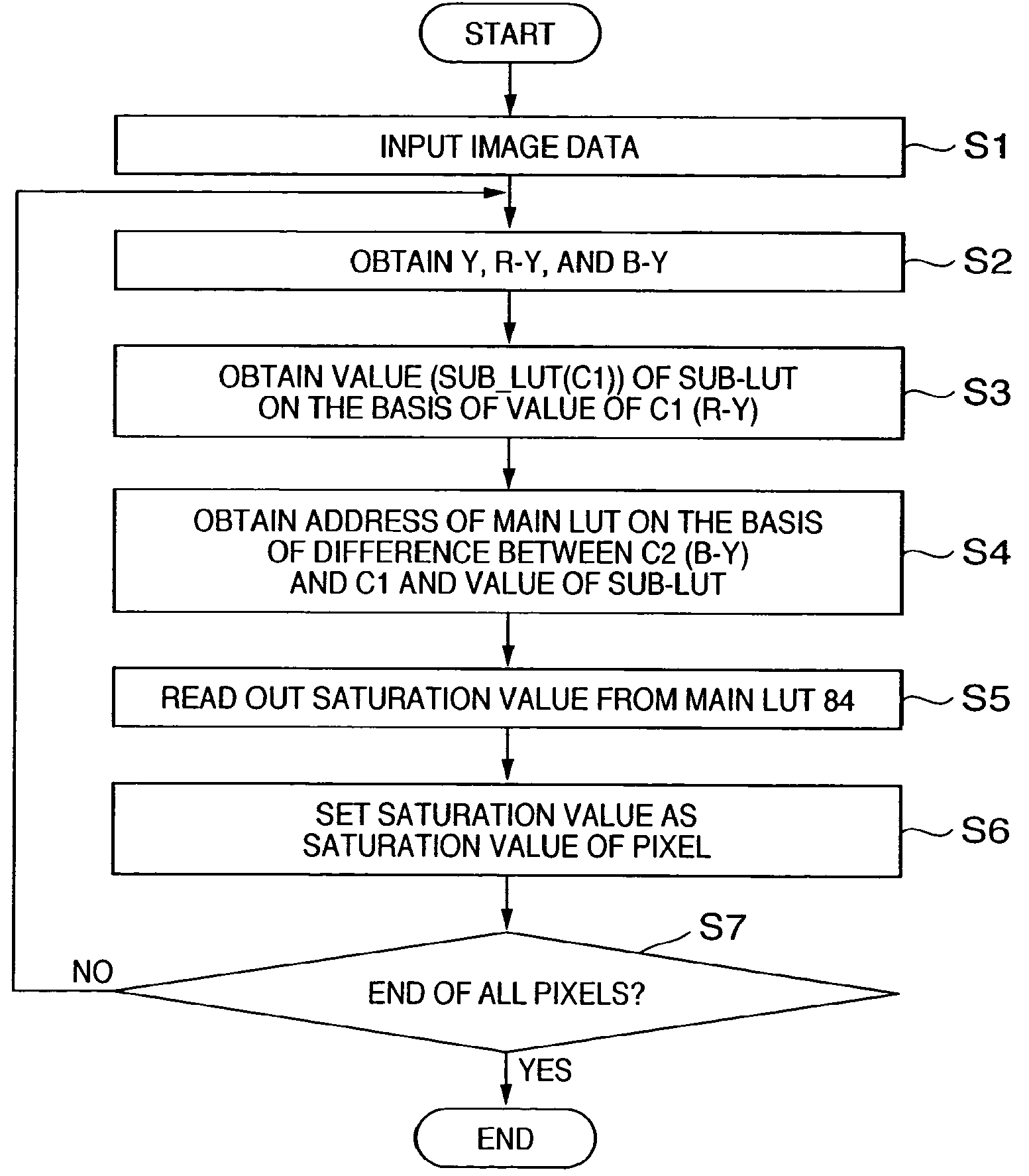
[0044]A method of obtaining the saturation in the YCC color space by utilizing the above-described principle will be explained.

[0045]Assume that a brightness and color difference signals for a 24-bit RGB image (8 bits for each color) are defined by

Y=0.3R+0.59G+0.11B

C1=INT[R−Y]

C2=INT[B−Y]

where INT[x] means converting x into an integer. If the color difference signal must have decimal-point precision, x is multiplied by an integer in advance in accordance with necessary precision. In the first embodiment, the right of the decimal point is simply discarded. In FIG. 3, the possible ranges of two color difference signals C1 and C2 are

−178≦C1≦179

−226≦C2≦227

The saturation is calculated by the root sum square, which does not depend on the sign apparently. Hence, an LUT suffices to be created for a hatched portion 300 in FIG. 3. The first embodiment assumes creation of an LUT in the region 300 above a straight line 301 having a slope of “1”. The maximum value of the absolute value of C1 is ...

second embodiment

[0054]The second embodiment of the present invention will be described as a method of obtaining the hue angle. The saturation described in the first embodiment apparently has symmetry. The hue angle H is given by

H=tan−1(C1 / C2)

and does not seem to have symmetry. However, from a different viewpoint, the hue angle H can be regarded to have symmetry. That is, the second embodiment utilizes the fact that the angle has periodicity and the trigonometric function has a certain sort of symmetry about a straight line having a slope of “1”.

[0055]An angle θ′ of a point Q (C2′,C1′) axisymmetrical about a straight line 600 having a slope of “1” can be calculated by (90°-0) using an angle θ stored in correspondence with a point P (C1,C2) in FIG. 6. Furthermore, the range is divided into eight regions (a) to (h) in accordance with the signs of the input values C1 and C2 and their magnitude relationship, as shown in FIG. 7. The hue angle of each region can be calculated as shown in FIG. 7 on the bas...


PUM


Abstract

In a color conversion method of inputting at least two color difference values and obtaining a corresponding saturation value, a main lookup table which stores the saturation value for the color difference values, and a sub-lookup table for obtaining an address for accessing the main lookup table, are created. An address to be used in accessing the main lookup table is determined on the basis of the sub-lookup table and the difference between the two color difference values, in correspondence with two arbitrary color difference values. A saturation value corresponding to the two color difference values is obtained from the determined address of the main lookup table.

Description

FIELD OF THE INVENTION[0001]The present invention relates to a technique of inputting at least two color difference values, obtaining a saturation value corresponding to these color difference values, and performing color correction and, more particularly, to a technique of efficiently calculating the saturation and hue angle in color information at high speed.BACKGROUND OF THE INVENTION[0002]Various methods and apparatuses have conventionally been proposed for color correction of a digital color image. In many color correction processes, the color is managed and corrected in terms of “three attributes of color”, i.e., brightness Y, hue angle H, and saturation S. A representative example is an L*a*b* color space. In this color space, the color can be processed by means of the three attributes, and the color can be intuitively managed and grasped. Digital color data is generally managed by R, G, and B signals. In practice, it is difficult theoretically to manage the color by means of...

Claims


Application Information

Patent Timeline
IPC IPC(8): G06K9/00G06T1/00H04N1/46H04N1/60H04N1/64
CPCH04N1/646H04N1/6005
Inventor YAMAZOE, MANABU
Owner CANON KK
Why Eureka
Try Eureka