Valve unit for pressure exchanger installations

a valve unit and pressure exchanger technology, applied in gravity filters, feed/discharge of settling tanks, loose filtering material filters, etc., can solve the problems of large dimensioning problems of the valve unit, the valve unit is only suitable for small reverse osmosis installations, etc., to achieve low cost, reduce the number of sealing locations on the valve unit, and avoid unfavorable undercuts

Inactive Publication Date: 2009-10-13
KSB AG
View PDF33 Cites 13 Cited by
  • Summary
  • Abstract
  • Description
  • Claims
  • Application Information

AI Technical Summary

Benefits of technology

[0008]The object of the invention is to provide a switch-over device or valve unit, particularly for large reverse osmosis pressure exchanger installations, which can distribute large fluid flows, simply and without difficulty, between different tubular chambers of the pressure exchanger.
[0009]In a valve unit of the aforedescribed type, the solution of this problem provides, within the housing, for a supply flow to the control element occurring from the axial and / or radial direction and an outlet flow occurring in the axial direction from the control element. A minimum installation length of the valve unit can be achieved in the case of axial supply and outlet flows. Although, in the case of radial supply flow, on the other hand, the valve unit is somewhat longer, the axial thrust which arises can be dealt with more easily.
[0010]One advantageous embodiment provides for the control element to be configured as a hollow cylindrical control element and for a separating wall dividing the hollow cylindrical control element into two spaces of different pressure regions. This permits the formation of additional spaces, in which a flow deflection occurs for a fluid to be exchanged, within the valve unit. In consequence, a simple, thin-walled component, which is easier to control during the switch-over processes, can be used for the actual control and sealing functions of the valve unit. To this end, a further embodiment provides for additional stiffening features to be arranged in the spaces of different pressure regions. Such stiffening features are configured as ribs or wall elements subdividing a pressure region through which flow occurs in the flow direction. The additional stiffening features can likewise be configured in the form of annular elements. These can be segments or peripheral parts. They improve the stiffness of the hollow cylindrical control element when it is subjected to different pressure ratios, thus resisting deformation of the component.

Problems solved by technology

This valve unit, however, is only suitable for small reverse osmosis installations because the flow cross sections within the valve unit are approximately the same size as the flow cross sections of the ducts to be filled.
In the case of large installations, and the fluid columns to be displaced in them and the forces caused by this, a substantial dimensioning problem arises for the valve unit.

Method used


Image

  • Valve unit for pressure exchanger installations
  • Valve unit for pressure exchanger installations
  • Valve unit for pressure exchanger installations

Examples


Embodiment Construction

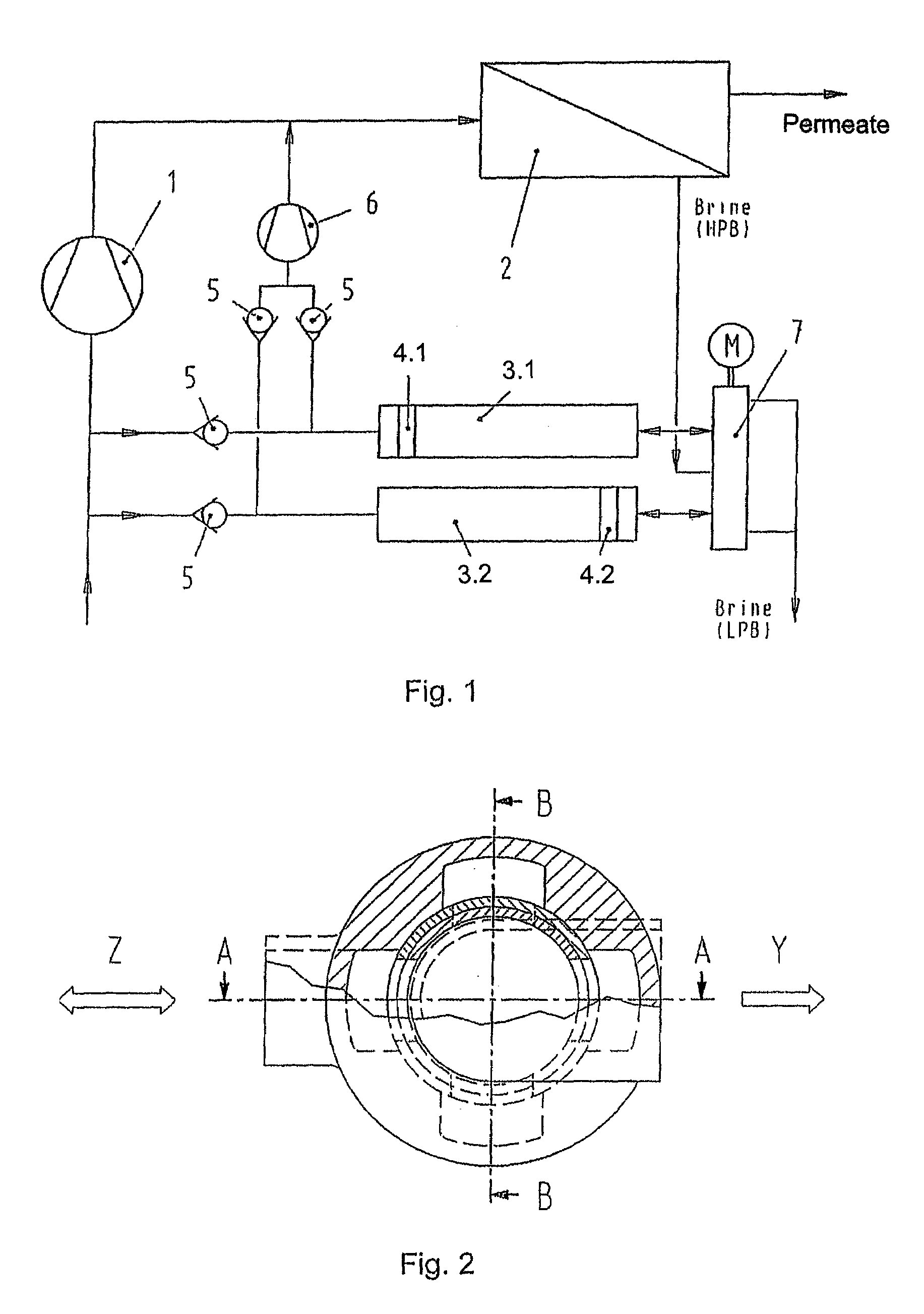
[0041]FIG. 1 shows a mode of operation of a valve unit according to the prior art, using a reverse osmosis installation as an example. A high-pressure pump 1 delivers a fluid which has to be cleaned, generally water in the form of lake water, sea water, brackish water or, indeed, drainage water, to one or a plurality of reverse osmosis modules 2. Because of the high osmotic pressure within this module 2, a separating effect occurs on the membranes arranged within it. Behind the membranes, cleaned water, the so-called permeate, flows away at low pressure, is collected and supplied for further use.

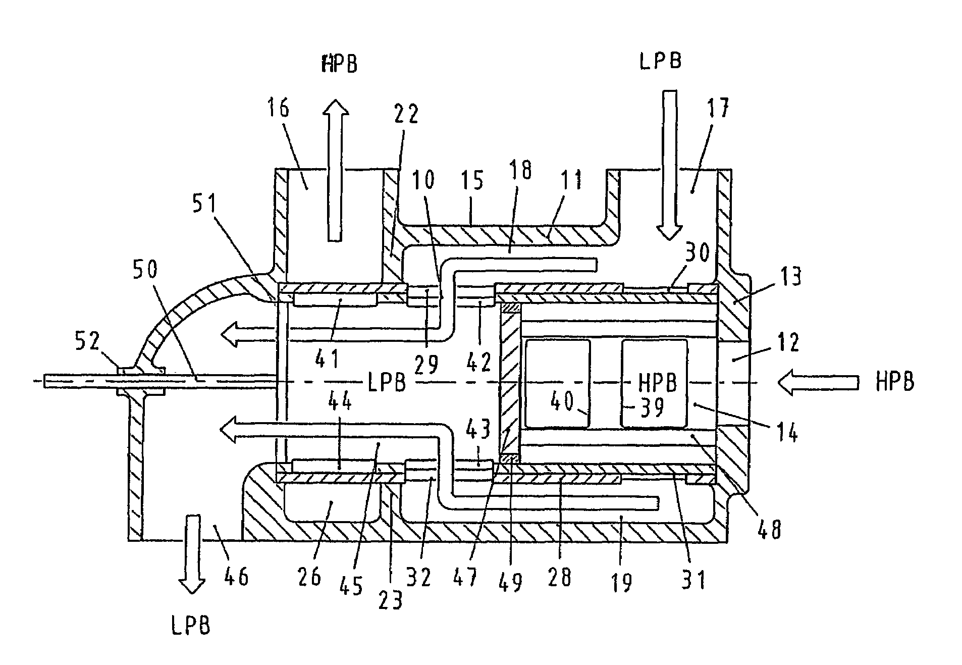
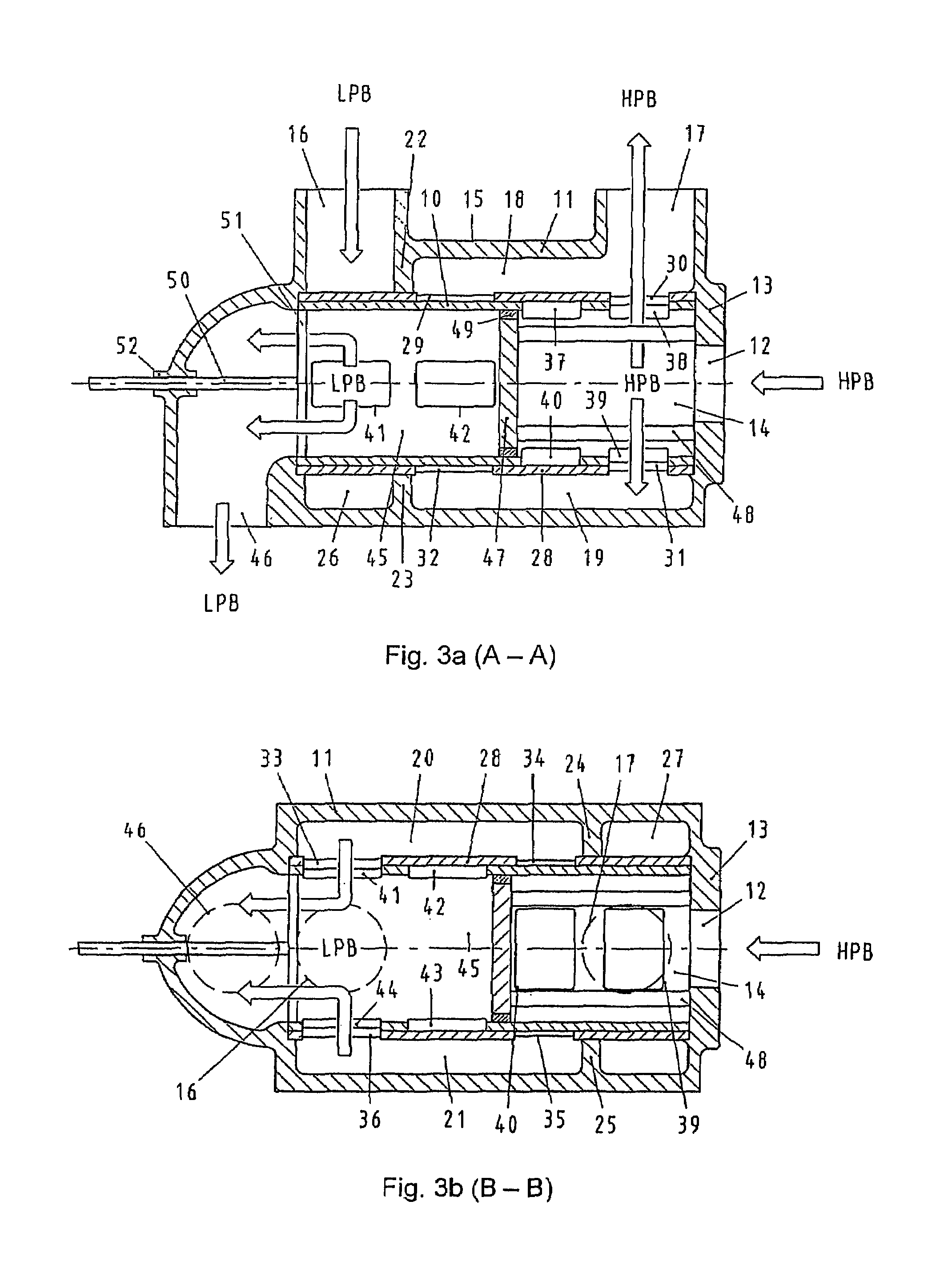
[0042]An unpurified fluid flowing away from the reverse osmosis modules 2, the so-called brine, has a higher concentration density of pollutants, generally salts, after the separation process and is conducted away to the original source. Because of its high energy content in the form of pressure energy, the brine is led via a valve unit 7 to the energy recovery process in a two-chamber press...


PUM

PropertyMeasurementUnit
inlet pressureaaaaaaaaaa
pressureaaaaaaaaaa

Abstract

A valve for switching over liquid paths, particularly for pressure exchanger installations with tubular pressure exchanger chambers (3) through which an alternating flow occurs, in which a rotatable control element (10, 10.1) having a plurality of flow paths is mounted in a housing (11), which in turn comprises a plurality of connection opening (12, 16, 17, 46) connected to a first pipe system and to an end of at least one pressure exchanger. Another end of the pressure exchanger is connected to a second pipe system through a valve. A motorized drive shaft (50) rotates the control element so as to alternately connect the control element flow paths to openings inside housing (11). Oncoming flow to the control element may come from an axial direction or from a radial direction, and outgoing flow from the control element occurs in the axial direction.

Description

CROSS REFERENCE TO RELATED APPLICATIONS[0001]This application is a continuation of international patent application no. PCT / EP2004 / 001532, filed Feb. 18, 2004 designating the United States of America, and published in German as WO 2004 / 080576 on Sep. 23, 2004, the entire disclosure of which is incorporated herein by reference. Priority is claimed based on Federal Republic of Germany patent application nos. DE 103 10 663.4 and DE 10 2004 002 547.9, filed Mar. 12, 2003 and Jan. 17, 2004, respectively.BACKGROUND OF THE INVENTION[0002]The invention relates to a valve unit, in particular for installations with pressure exchangers with tubular chambers through which flow occurs alternately, a rotatable control element with a plurality of flow paths being arranged within a housing, the housing having a plurality of connections for connection lines, the housing being connected to a first pipe system and, in each case, with an end of at least one tubular chamber, a respective other end of a ...

Claims


Application Information

Patent Timeline
Patent Type & Authority Patents(United States)
IPC IPC(8): F16K11/083B01D61/02B01D61/06B01D61/10F16K11/085
CPCB01D61/06F16K11/085B01D61/10Y10T137/86566Y10T137/86863Y10T137/86839
Inventor BAUMGARTEN, SVENBROSS, STEPHANBRECHT, BERNHARDBRUHNS, UWEFLAK, STEFANJAEGER, CHRISTOPHKOCHANOWSKI, WOLFGANGKNOEBL, WILTRUDELLEGAARD, MOGENS
Owner KSB AG
Why Eureka
Try Eureka