
Liquid crystal display and a driving method thereof

a technology of liquid crystal display and driving method, which is applied in the direction of suction pumps, instruments, other medical devices, etc., can solve the problems of inability to correct gray display, complicated manufacturing techniques of lcd using color filter methods, and inability to improve the filter itself, so as to achieve the effect of improving brightness

Inactive Publication Date: 2009-10-13
SAMSUNG DISPLAY CO LTD
View PDF13 Cites 28 Cited by
  • Summary
  • Abstract
  • Description
  • Claims
  • Application Information

AI Technical Summary

Benefits of technology

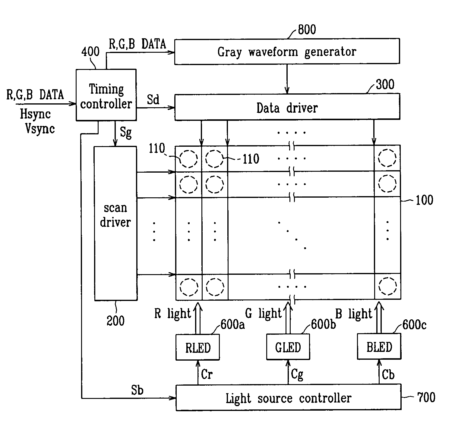
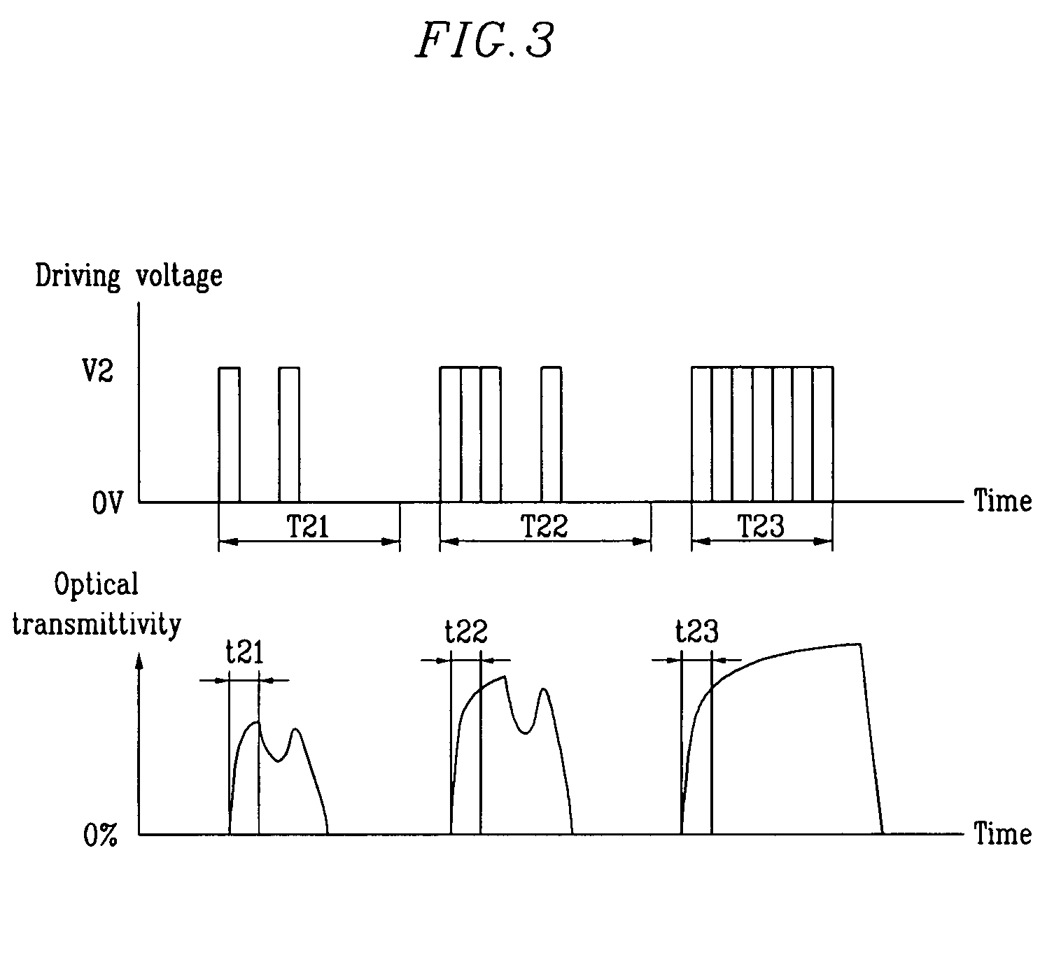
[0028]In the present invention, there is provided a field sequential driving type liquid crystal display for achieving both improvement of brightness and correct gray display simultaneously that overcomes the above-described shortcomings of the liquid crystal display while retaining their advantages.

Problems solved by technology

An LCD device displaying color using a single light source and three (3) color filter layers needs a unit pixel corresponding to each of R, G, and B subpixels, thus at least three (3) times the number of pixels are needed compared with displaying only black and white, therefore, making the techniques of manufacturing an LCD using the color filter method more complicated.
Further complicating the matters, there are problems in that separate color filter layers need to be formed on the substrate for an LCD during manufacturing, and the light transmission rate of color filter itself needs to be improved.
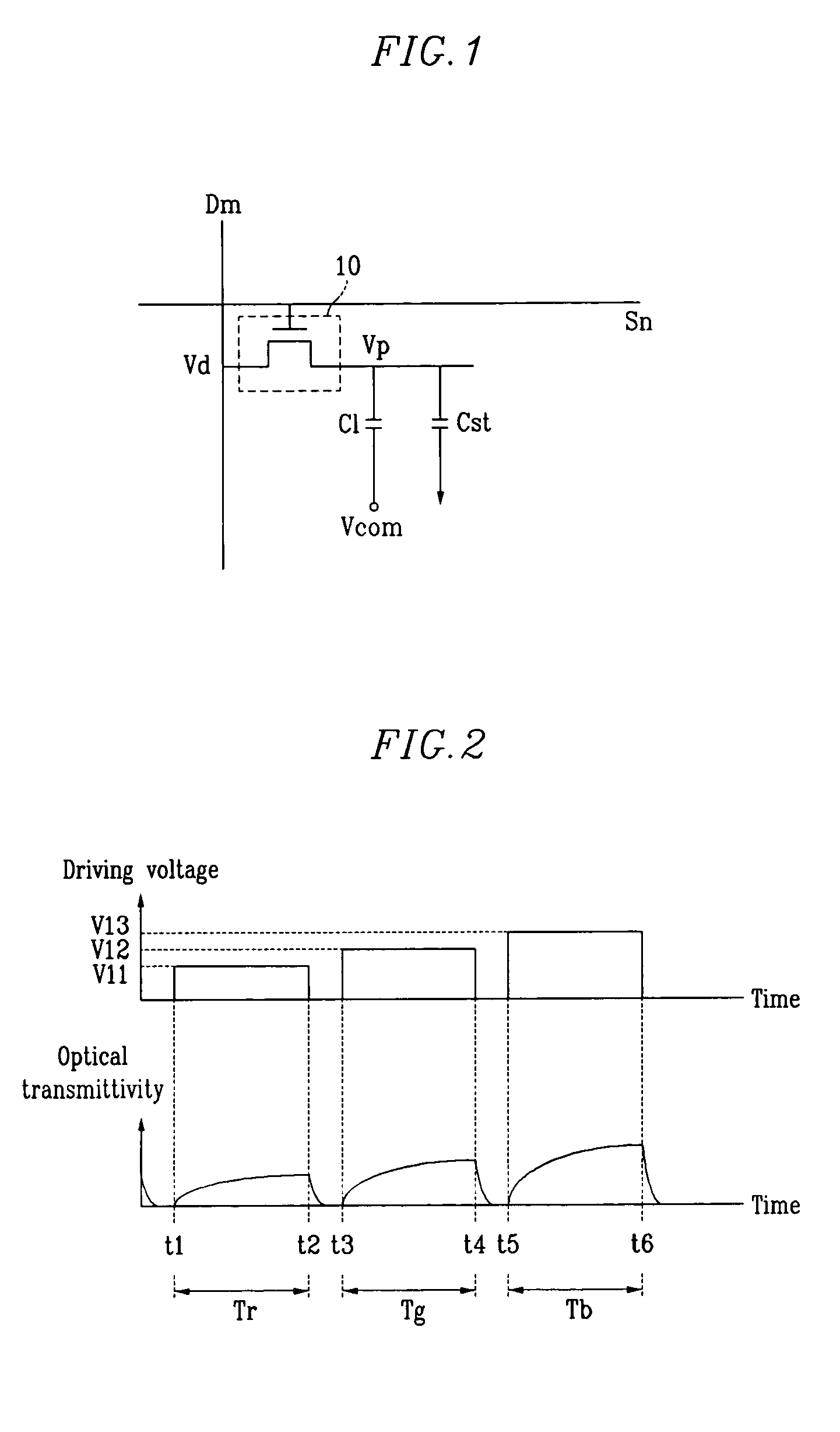
Regardless of whether the driving method is analog or digital, in a conventional field sequential driving method, correct gray display is not possible since an effective value response of a desired gray for display (for example, a gray of R) is changed by a previous gray display (for example, a gray of G).
Thus, during the reset period of the above method, there is a problem in which brightness is poor, compared with driving methods which do not use application of a reset voltage.

Method used


Image

  • Liquid crystal display and a driving method thereof
  • Liquid crystal display and a driving method thereof
  • Liquid crystal display and a driving method thereof

Examples


Embodiment Construction

[0045]In the following detailed description, only certain exemplary embodiments of the invention are shown and described. As those skilled in the art would realize, the described embodiment may be modified in various different ways, all without departing from the spirit or scope of the present invention. Accordingly, the drawings and description are to be regarded as illustrative in nature, and not restrictive. In addition, to clarify the present invention, certain components which are not described in the specification can be omitted, and like reference numerals indicate like components.

[0046]Moreover, in the context of certain discussions of the present application, reset refers to applying a voltage (or waveform) to make liquid crystal materials in an LCD form a black state such that light transmission is blocked (e.g., optical transmittivity is almost zero (0)). Gray voltage refers to voltages having different voltage levels from each other, and gray waveform refers to waveforms...


PUM

PropertyMeasurementUnit
voltageaaaaaaaaaa
optical transmittivityaaaaaaaaaa
constant pulse widthaaaaaaaaaa

Abstract

A method for driving a liquid crystal display is provided. The display includes a liquid crystal formed between a first substrate and a second substrate, a first electrode arranged at the first substrate, a second electrode arranged at the second substrate, and red, green, and blue lights sequentially transmitting on one pixel of the display. The driving method includes applying a gray voltage based on gray data between the first electrode and the second electrode during a first part in a first period and applying a reset voltage to reset a liquid crystal between the first electrode and the second electrode to a desired state during a second part in the first period.

Description

CROSS REFERENCE TO RELATED APPLICATION[0001]This application claims priority to and the benefit of Korea Patent Application No. 10-2004-0037275 filed on May 25, 2004 in the Korean Intellectual Property Office, the entire content of which is incorporated herein by reference.BACKGROUND OF THE INVENTION[0002](a) Field of the Invention[0003]The present invention relates to a liquid crystal display and a driving method thereof. More specifically, the present invention relates to a field sequential driving type liquid crystal display (FS-LCD), and a driving method thereof.[0004](b) Description of the Related Art[0005]As personal computers and televisions, etc. become more lightweight and thin, their display devices should also be lightweight and thin. Accordingly, flat panel displays such as liquid crystal displays (LCDs), which are both light weight and thin, have recently been developed for these computers and televisions in place of cathode ray tubes (CRTs).[0006]An LCD is a display de...

Claims


Application Information

Patent Timeline
Patent Type & Authority Patents(United States)
IPC IPC(8): G09G3/36G02F1/133G09G3/20G09G3/34
CPCG09G3/3413G09G3/3648G09G2310/0235G09G2320/0646G09G2310/061G09G2310/08G09G2320/0242G09G2310/024A61M1/08A61M2205/07A61M1/74A61M1/80
Inventor PARK, JUN-HO
Owner SAMSUNG DISPLAY CO LTD
Learn More