Method and apparatus for adjusting the contrast of an image

a technology of contrast adjustment and image, applied in image data processing, television systems, instruments, etc., can solve the problems of large gain, excessive or poor lighting conditions, ringing or over/under shooting effects around the edges or other regions of high contrast, etc., to achieve good adaptation of delay coefficient, good results, and high contrast

Active Publication Date: 2009-10-13
VESTEL ELEKTRONIK SANAYI & TICARET ANONIM SIRKETI
View PDF6 Cites 25 Cited by
  • Summary
  • Abstract
  • Description
  • Claims
  • Application Information

AI Technical Summary

Benefits of technology

[0010]By using a recursive infinite impulse response filter having a single delay coefficient, the computational complexity of the filtering process is minimised, which allows the method to be carried out quickly and / or with lower cost processing equipment. This makes it economic to implement the method in consumer equipment, such as a television receiver that receives and processes digital image signals. Because the delay coefficient is adaptive to areas of high contrast, the method of the present invention allows local contrast enhancement to be achieved in which for example edges in the input image are preserved whilst mid-range contrast details are filtered out. The method is therefore less prone to producing over / under shooting artefacts and other noise in the output image.
[0014]As is known per se, a filter of this type can give rise to an unwanted phase delay. By using two filters which are run in opposite directions across the pixels, and by averaging the outputs of the two filters, the phase delays of the two filters can effectively be made to cancel each other out. The “lines” of pixels may be for example rows of pixels or columns of pixels. In a preferred embodiment, filtering is carried out (separately) for both the rows and the columns of pixels.
[0024]These preferred functions for the delay coefficient used at each pixel provide for good adaptation of the delay coefficient to deal with edges and other regions of high contrast in the input image. The value of the delay coefficient at an edge, for example, can be made to decrease strongly, thus preserving the edge in the output image. In an example, α has a value between 5 and 9. A value of 7 for a has been found to produce particularly good results.
[0025]In an embodiment, the high frequency component is amplified by a gain that is a function of the magnitude of the difference between the local mean of brightness level data and the input brightness level at said pixel. This helps to prevent further the production of unwanted artefacts in the output image.

Problems solved by technology

Global contrast enhancement techniques remedy problems that manifest themselves in a global fashion, such as excessive or poor lighting conditions in the source environment.
This causes ringing or over / under shoot effects around the edges or other regions of high contrast in the original image because of the high values of the high frequency component around the edges after the amplification.
However, this causes the gain to become very large when the local variance is small, which leads to noise amplification in smooth (low contrast) areas of the input image 1.
However, the filter that is disclosed in this paper is a Laplacian filter which therefore has three tap coefficients and which is therefore computationally complex.

Method used


Image

  • Method and apparatus for adjusting the contrast of an image
  • Method and apparatus for adjusting the contrast of an image
  • Method and apparatus for adjusting the contrast of an image

Examples


Embodiment Construction

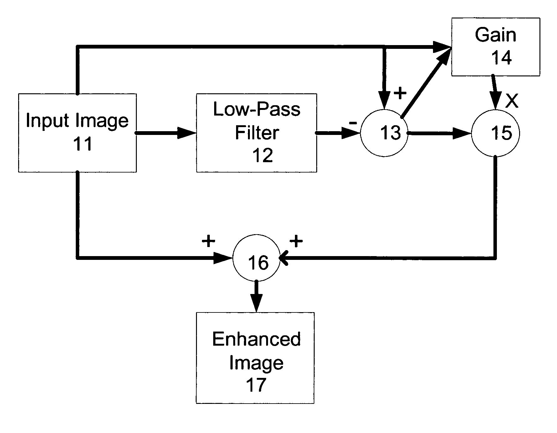
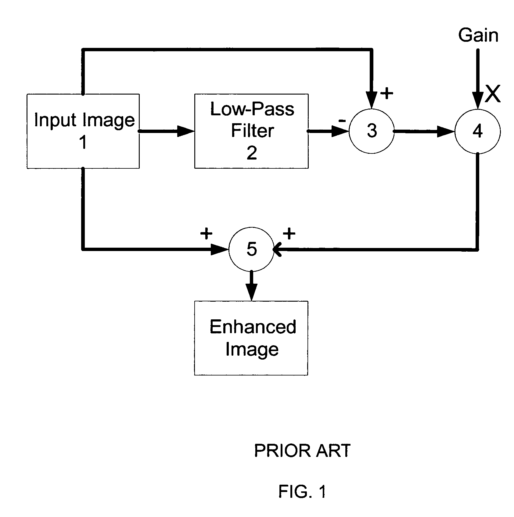
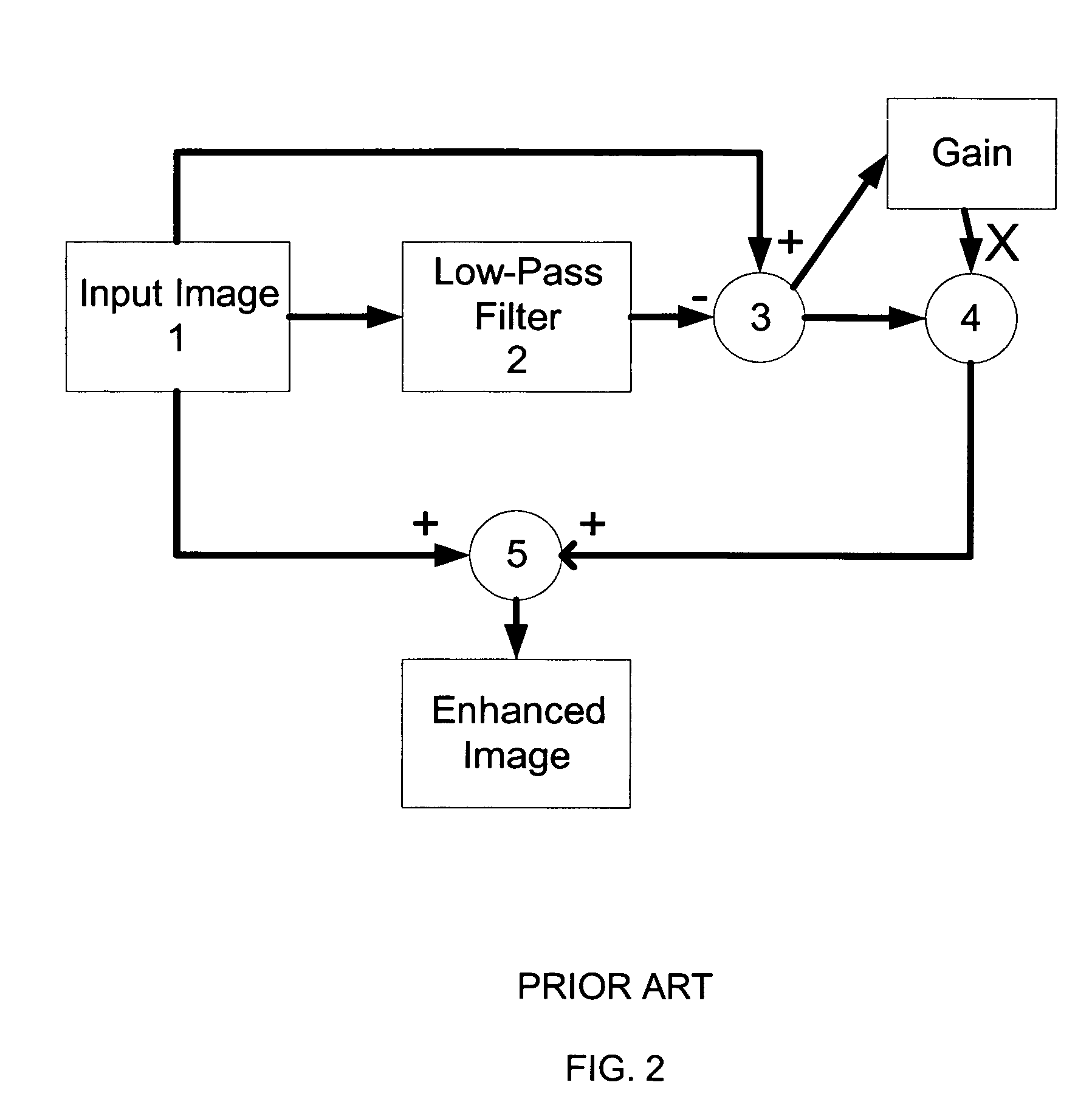
[0047]Referring to FIG. 3, which shows schematically an overview of an example of a method according to the present invention, an original input image 11 is filtered by a low pass filter 12 which effectively removes the sharp or high frequency component of the input image 11 to leave an unsharp or low frequency image. This unsharp image is subtracted from the original image 11 in a summer 13, which therefore outputs the high frequency component. The high frequency component is multiplied with a gain factor obtained from a gain calculator 14 in an amplifier 15. The amplified high frequency component of the image is then added back to the original input image 11 in a second summer 16, which outputs the enhanced image 17. The gain that is provided by the gain calculator 14 is varied in the preferred embodiment, as will be discussed further below.

[0048]In adaptive contrast enhancement, mathematically the enhanced or output image y(m,n) is obtained from the input image x(m,n) as:

y(m,n)=μ...


PUM


Abstract

A method and apparatus for adjusting the contrast of an input image is disclosed. Brightness level data of the input image is filtered to obtain at least a low frequency component and a high frequency component. The high frequency component is amplified. The input image and the amplified high frequency component are summed to produce brightness level data of the output image. The filtering is carried out by at least one recursive infinite impulse response filter having a single delay coefficient that is adaptive to areas of high contrast in the input image.

Description

CROSS-REFERENCE TO RELATED APPLICATIONS[0001]Not applicable.STATEMENT REGARDING FEDERALLY SPONSORED RESEARCH OR DEVELOPMENT[0002]Not applicable.TECHNICAL FIELD OF THE INVENTION[0003]The present invention relates to a method and apparatus for adjusting the contrast of an image.BACKGROUND OF THE INVENTION[0004]A number of techniques are known for adjusting the contrast of an image, particularly in order to improve the contrast and therefore visibility of the image. Contrast adjustment or enhancement of images, particularly digital images, is used in many fields, including enhancing the contrast of a digital image for display by a television receiver or other display device, for printing by a printer, in digital cameras, etc., etc. Contrast enhancement is used to improve the contrast in medical and other images.[0005]Global contrast enhancement techniques remedy problems that manifest themselves in a global fashion, such as excessive or poor lighting conditions in the source environmen...

Claims


Application Information

Patent Timeline
Patent Type & Authority Patents(United States)
IPC IPC(8): H04N5/57
CPCH04N5/20G06T5/004
Inventor ARICI, TARIKAKGUN, TOYGARALTUNBASAK, YUCEL
Owner VESTEL ELEKTRONIK SANAYI & TICARET ANONIM SIRKETI
Why Eureka
Try Eureka