Harmonic engine

a technology of engine and heat, applied in the direction of steam engine plants, machines/engines, mechanical equipment, etc., can solve the problems of affecting the thermal efficiency of the engine, causing a significant loss of thermal efficiency, and causing a greater frictional power loss in the system than is necessary

Inactive Publication Date: 2009-10-20
LAWRENCE LIVERMORE NAT SECURITY LLC
View PDF16 Cites 67 Cited by
  • Summary
  • Abstract
  • Description
  • Claims
  • Application Information

AI Technical Summary

Benefits of technology

[0015]Another aspect of the present invention includes an engine comprising: a reciprocating-piston expander comprising: an expander cylinder enclosing a cylindrical volume; an expander piston head axially slidable in said expander cylinder and dividing the cylindrical volume into an enclosed expansion chamber and an enclosed buffer chamber; a piston rod connected at one end to the expander piston head and axially extending out from the expander cylinder through a closed end thereof; an inlet valve for controlling the flow of working fluid into the expansion chamber to effect a power stroke of the expander, said inlet valve being a harmonic oscillator having an equilibrium position outside the expansion chamber so that the inlet valve is open at equilibrium and displaceable to a closed position against an equilibrium restoring force; latch means for automatically re-latching the inlet valve in the closed position after being unlatched to experience a harmonic oscillation; an outlet valve for controlling the flow of working fluid out from the expansion chamber during a return stroke of the expander, said outlet valve being a harmonic oscillator having an equilibrium position inside the expansion chamber so that the outlet valve is open at equilibrium and displaceable to a closed position against an equilibrium restoring force; an intake header connectable to a pressurized fluid source for channeling pressurized working fluid into the expansion chamber via the inlet valve; and an exhaust header for channeling working fluid exhausted out from the expansion chamber via the outlet valve; and a shunt channel fluidically connecting the buffer chamber to the exhaust header so that, upon operating said outlet valve to exhaust working fluid from the expansion chamber, the expansion chamber and the buffer chamber are in fluidic communication; periodic return means for effecting the return stroke of the expander after each power stroke; a compressor as the pressurized fluid source having a compression chamber, a compressor inlet leading into the compression chamber, and a compressor outlet leading out from the compression chamber; a fluidic channel connecting the compressor outlet to the intake header of the expander for supplying pressurized working fluid thereto; throttle valve means for controlling the flow rate of working fluid entering the compressor based on an absolute temperature ratio of the working fluid leaving the expander and the working fluid entering the compressor; and throttle valve means for controlling the flow rate of working fluid coming from the exhaust header of the expander.

Problems solved by technology

However, a drawback of this single cylinder arrangement is the significant flow of heat from the high temperature expander chamber to the low temperature compressor chamber via the cylinder wall and the piston, which incurs a significant loss of thermal efficiency.
As a result, pressure variations in the fluid circuit are produced that may be detrimental to the thermal efficiency of the engine.
Furthermore, the use of an expander cross head linkage 60 and a separate compressor cross head linkage 61, may make the frictional power loss in the system greater than necessary.
Finally, the extra mechanisms associated with the extra cross head entail greater expense and less reliability than would be the case with a single cross head
However, similar to the Bush patent, pressure swings in the fluid volume linking the two tandem cylinders of FIG. 3 can produce degradation in the thermal efficiency associated with the fact that the rate at which air is expelled from the compressor does not necessarily match the rate at which air is optimally ingested into the expander.
Furthermore, one of the most complicated and expensive features in the prior art of heat powered engines is the expander valve actuation mechanism.
However, because of the sliding contact, such Dee valves must be lubricated to prevent undo friction, and are not able to function reliably at high speed and temperature.
However, Bush does not teach how the expander inlet and outlet valves may be made to act fully automatically, as has long been known in the art for compressor valves.
However, this prior art does not teach the use, or particular advantages of resonantly acting, harmonic oscillator valves in the expander of an external heat powered engine.

Method used


Image

  • Harmonic engine
  • Harmonic engine
  • Harmonic engine

Examples


Embodiment Construction

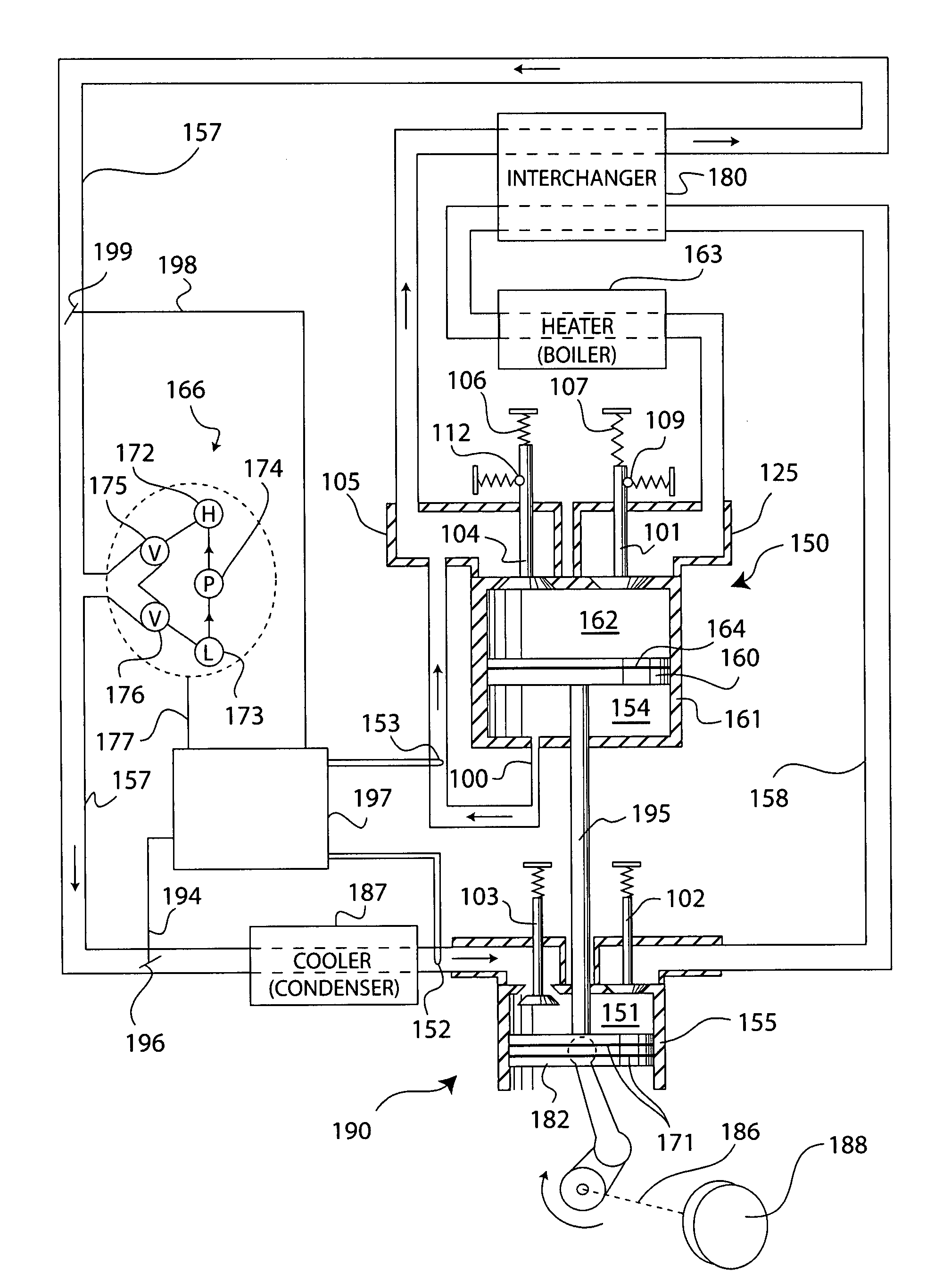
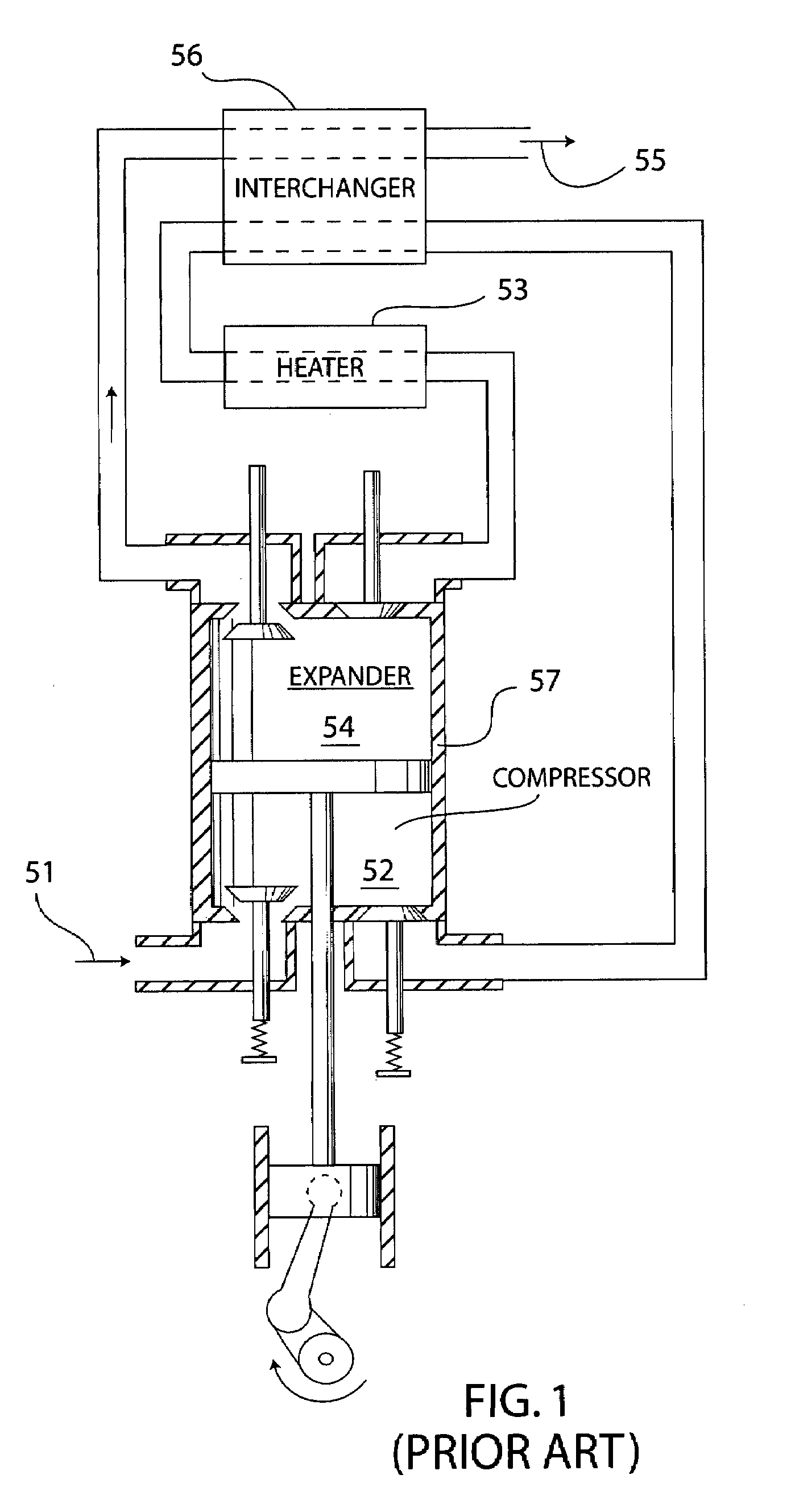
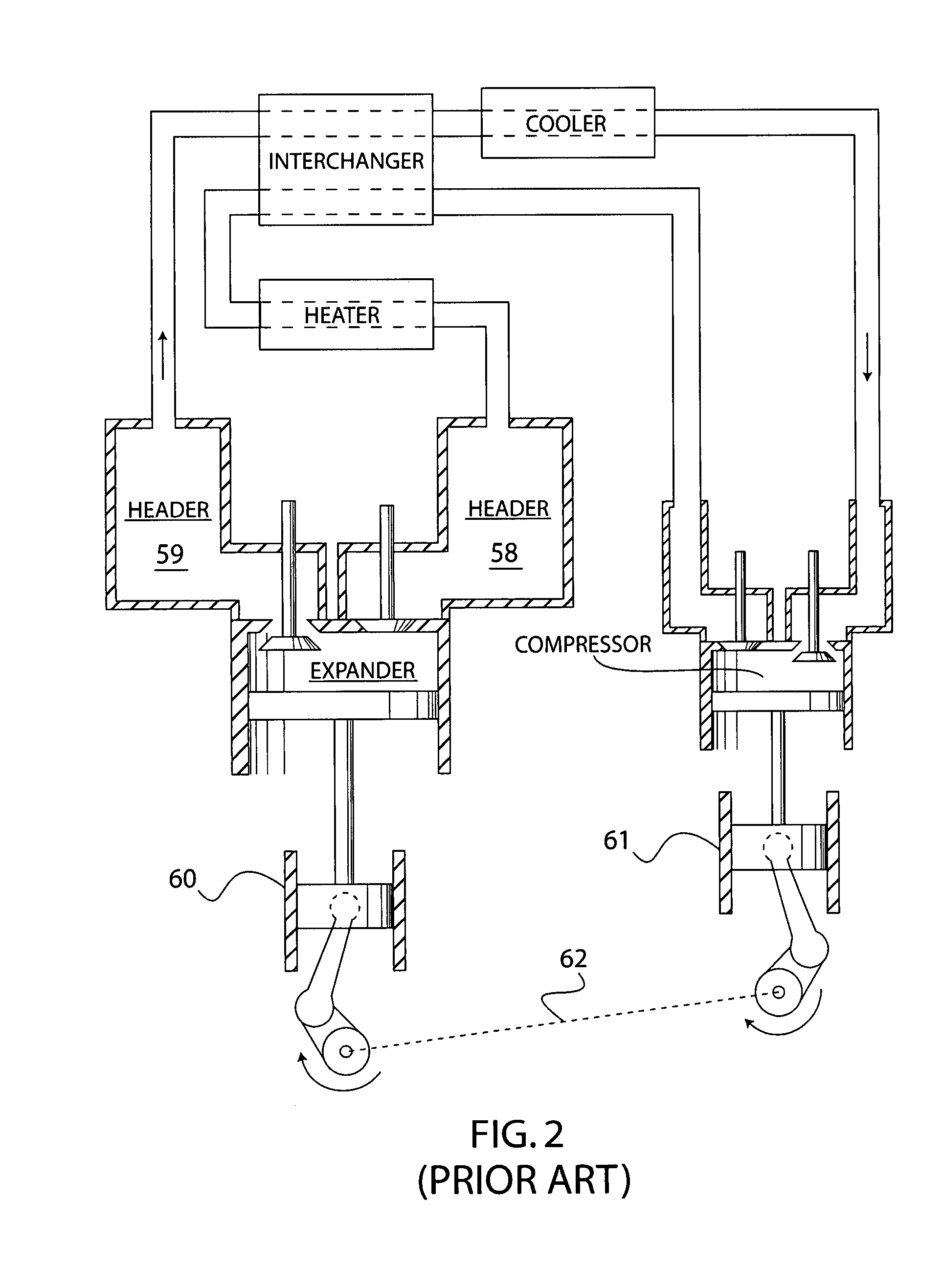
[0033]Generally, the present invention is a high efficiency, heat powered reciprocating-piston engine designed to maximize thermal efficiency by minimizing thermal losses and pressure hysteresis losses as much as reasonably achievable, as well as enabling automatic self-acting expander valve actuation for simplified and cost-effective operation. The engine expander and compressor cylinders of the engine are separated in order to minimize the heat loss from the hot end to the cold end of the engine. In particular, the separation enables the harmonic engine to operate at very high thermal efficiency by allowing a high ratio between the hot side temperature and the cold side temperature in the engine. By virtue of the extreme temperature capability of this engine, thermal efficiency substantially exceeding 60%, the current state of the art value attained with gas turbine plus steam turbine combined cycle engines, is enabled. Experiments with a laboratory prototype based on the engine d...


PUM


Abstract

A high efficiency harmonic engine based on a resonantly reciprocating piston expander that extracts work from heat and pressurizes working fluid in a reciprocating piston compressor. The engine preferably includes harmonic oscillator valves capable of oscillating at a resonant frequency for controlling the flow of working fluid into and out of the expander, and also preferably includes a shunt line connecting an expansion chamber of the expander to a buffer chamber of the expander for minimizing pressure variations in the fluidic circuit of the engine. The engine is especially designed to operate with very high temperature input to the expander and very low temperature input to the compressor, to produce very high thermal conversion efficiency.

Description

I. FEDERALLY SPONSORED RESEARCH OR DEVELOPMENT[0001]The United States Government has rights in this invention pursuant to Contract No. W-7405-ENG-48 between the United States Department of Energy and the University of California for the operation of Lawrence Livermore National Laboratory.II. BACKGROUND OF THE INVENTION[0002]A. Technical Field[0003]This invention relates to heat powered engines, and more particularly to a highly efficient form of heat powered, reciprocating-piston, harmonically acting engine having, in one embodiment, harmonic oscillator valves automatically controlling working fluid flow into and out of an expander at a resonant frequency, and in another embodiment, a shunt channel connecting a buffer chamber of the expander to the outlet of an expansion chamber of the expander, to minimize pressure perturbation in the engine fluidic circuit.[0004]B. Description of the Related Art[0005]Heat powered engines are known in which heat is supplied externally of the workin...

Claims


Application Information

Patent Timeline
Patent Type & Authority Patents(United States)
IPC IPC(8): F01B29/10
CPCF01L1/46F01L3/20F02G1/04F01L3/24F01L2003/258F01L3/22
Inventor BENNETT, CHARLES L.
Owner LAWRENCE LIVERMORE NAT SECURITY LLC
Why Eureka
Try Eureka