Vehicle fairing structure

a technology for fairings and vehicles, applied in vehicle arrangements, roofs, transportation and packaging, etc., can solve the problems of increasing fuel consumption, increasing the cost of operation, and increasing the amount of power needed to move a vehicle over land or through the air, so as to reduce the aerodynamic drag

Active Publication Date: 2009-10-20
ZF COMPOSITES NORTH AMERICA LTD
View PDF48 Cites 84 Cited by
  • Summary
  • Abstract
  • Description
  • Claims
  • Application Information

AI Technical Summary

Benefits of technology

[0010]In one aspect, the invention is a vehicle fairing structure for a vehicle having a front vehicular component and a rear vehicular component (such as a tractor-trailer). The fairing structure comprises: a top surface (sometimes referred to herein as the “horizontal surface”) adapted to be attached to the roof, or the top, of the rear vehicular component, and two side surfaces (sometimes referred to herein as the “vertical surfaces”) each adapted to be attached to respective sides of the rear vehicular component, joining opposite ends of the top surface and generally perpendicular to the top surface. Each of the top and side surfaces has a proximal edge adapted to be positioned adjacent the vehicle, and a distal edge adapted to be positioned away from the vehicle with respect to the respective proximal edge. The area bounded by the distal edges of the surfaces is smaller than an area bounded by the proximal edges. The fairing structure is positioned adjacent a rear vehicular component (in preferred embodiments the front of a trailer box) in a gap between the rear vehicular component and a front vehicular component (such as a tractor cab), sufficiently close to said front vehicular component to impede or otherwise lessen transverse and vertical airflow in the gap, lessening aerodynamic drag. This is accomplished by positioning the distal and proximal edges of the surfaces relative to each other such that the external faces of the fairing structure, when positioned adjacent the rear vehicular component of the vehicle in the gap, re-directs air from the rear vehicular component and also impedes or otherwise lessens vertical and transverse air flow in the gap, forming an effective closure of the gap.

Problems solved by technology

The amount of power needed to move a vehicle over land or through the air increases with the speed of the vehicle due to aerodynamic drag.
The amount of power necessary to overcome aerodynamic drag directly translates into increased fuel consumption, and thus cost of operation.
While this fairing structure significantly reduces drag at the rear end of the trailer box, a significant amount of drag is also associated with the front of the trailer box where there is known to be an area of high pressure and relatively stagnant air approximately at the middle of the forward vertical face of the trailer cab.
Accordingly, fairing structures designed to direct airflow around the gap have not been completely successful.
On the one hand, known fairing structures for the forward face of a trailer box can be bulky and complex, involving moving parts.
They may be difficult to install or impede access to important parts of the rig.
A less obtrusive fairing structure, on the other hand, may be less effective in redirecting wind and more susceptible to the negative effects of crosswind conditions.

Method used


Image

  • Vehicle fairing structure
  • Vehicle fairing structure
  • Vehicle fairing structure

Examples


Embodiment Construction

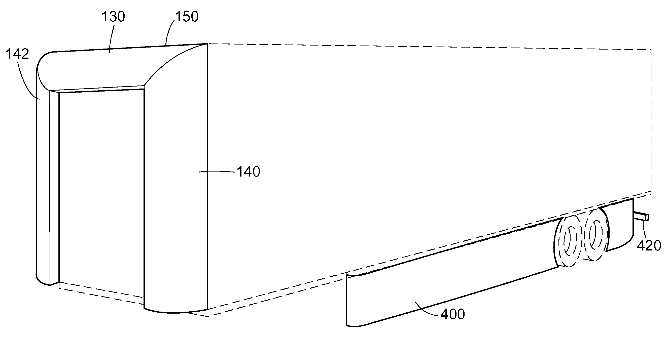
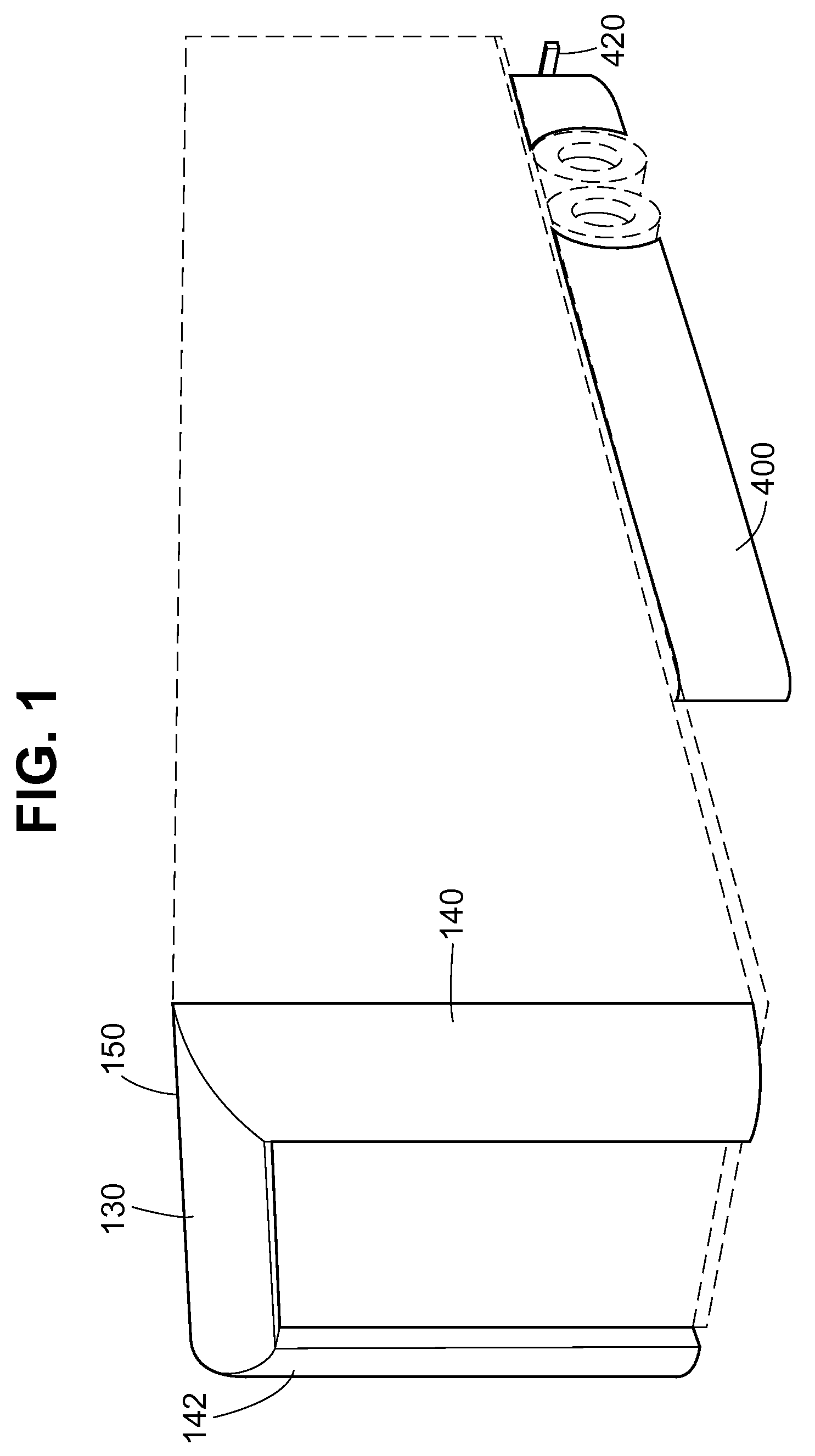
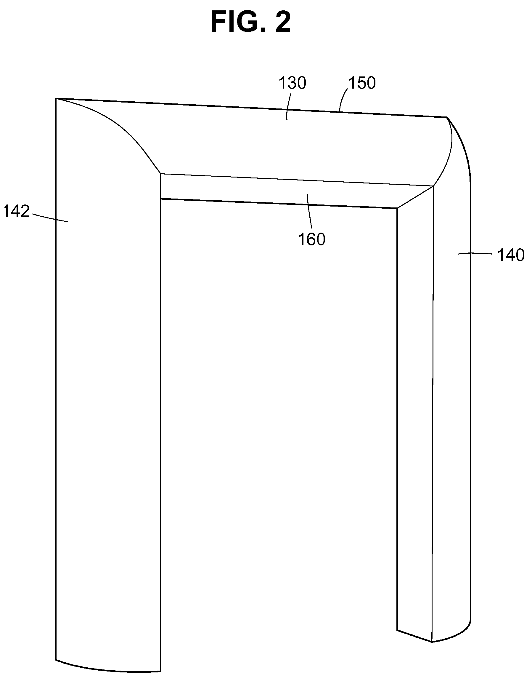
[0016]While the preferred embodiment of the invention is described in connection with a tractor-trailer combination, a fairing structure according to the invention may be used with any tandem vehicle arrangement. The invention is particularly suited for use on a tandem vehicle combination having a front vehicular component and a rear vehicular component connected to the front vehicular component. In such tandem vehicle arrangements, the rear vehicular component often projects above the front vehicular component and thus causes additional aerodynamic drag of a type referred to as form drag. Also, in such tandem vehicle arrangements, the rear vehicular component is separated from the front vehicular component by a gap, which also creates aerodynamic drag. The fairing structure is preferably positioned on the front of the rear vehicular component, and addresses both of these drag-producing factors.

[0017]To describe the drag created by the gap, the near wake of a bluff backed object lik...


PUM


Abstract

A vehicle fairing structure has a top fairing surface adapted to be attached to a trailer box, and first and second side fairing surfaces adapted to be attached to the sides of the trailer box, in the gap between a tractor cab and a trailer box in a tractor-trailer combination. The fairing structure directs air flow away from the gap, and is positioned in the gap to lessen aerodynamic drag, thereby reducing fuel consumption.

Description

[0001]This application claims the benefit of priority of U.S. Provisional Application No. 60 / 844,511 and U.S. Provisional Application No. 60 / 844,442, each filed Sep. 13, 2006, and which are each incorporated by reference herein.BACKGROUND OF THE INVENTION[0002]1. Field of the Invention[0003]This invention relates to structures for improving the aerodynamic profile of vehicles, especially for the front end of a trailer box in a tractor-trailer combination.[0004]2. Description of Related Art[0005]The amount of power needed to move a vehicle over land or through the air increases with the speed of the vehicle due to aerodynamic drag. The amount of power necessary to overcome aerodynamic drag directly translates into increased fuel consumption, and thus cost of operation.[0006]A variety of innovations aimed at reducing the aerodynamic drag of various transport vehicles, including tractor-trailer combinations, have been introduced in the prior art. These include efforts to make the hood,...

Claims


Application Information

Patent Timeline
Patent Type & Authority Patents(United States)
IPC IPC(8): B62D35/00
CPCB62D35/001
Inventor REIMAN, JAMESHEPPEL, PETER
Owner ZF COMPOSITES NORTH AMERICA LTD
Why Eureka
Try Eureka