Eccentrically oscillating gear device

a gear device and eccentric technology, applied in the direction of gearing, toothed gearings, shafts and bearings, etc., can solve the problems of increasing the number of parts and losing and achieve the effect of enhancing the degree of design freedom and reducing the number of parts

Inactive Publication Date: 2009-10-20
NABLESCO CORP
View PDF8 Cites 17 Cited by
  • Summary
  • Abstract
  • Description
  • Claims
  • Application Information

AI Technical Summary

Benefits of technology

[0008]According to the eccentrically oscillating gear device, the internal gear pins are received and supported by the receiving portions formed at the end face portions at the external-gear side of the pair of bearings. Therefore, when there is adopted the structure that the tooth top portions of the external gear is cut out, the internal gear pins under an idling state with respect to the external gear is regulated in the movement to the carrier side. Therefore, the pin press member used in the prior art can be omitted, and the degree of freedom in design can be enhanced. In addition, the device can be structurally shortened in the axial direction by the amount corresponding to the pin press member. Furthermore, the receiving portion brings the bearing with the pin press function. Therefore, it is unnecessary to use a dedicated part, so that the number of parts can be reduced and the cost merit can be achieved.
[0010]According to the eccentrically oscillating gear device of the present invention, when the structure that the tooth top portions of the external gear are cut out is adopted, the pin press member used in the prior art can be omitted, so that the number of parts can be reduced and the degree of freedom of design can be enhanced.

Problems solved by technology

However, when pin press members such as the pin press rings 55 to 57 shown in FIGS. 5 and 6 are used, the number of parts is increased, and also the device is designed to be large in the axial direction P, so that the degree of freedom of design is lost.

Method used


Image

  • Eccentrically oscillating gear device
  • Eccentrically oscillating gear device
  • Eccentrically oscillating gear device

Examples


Embodiment Construction

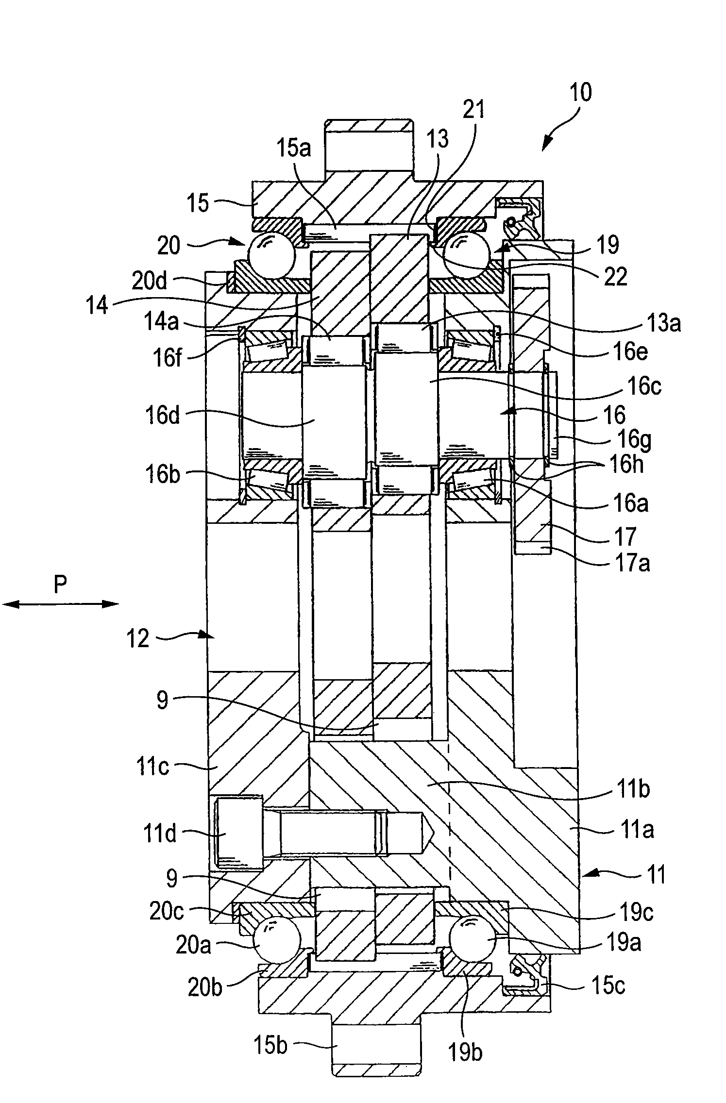
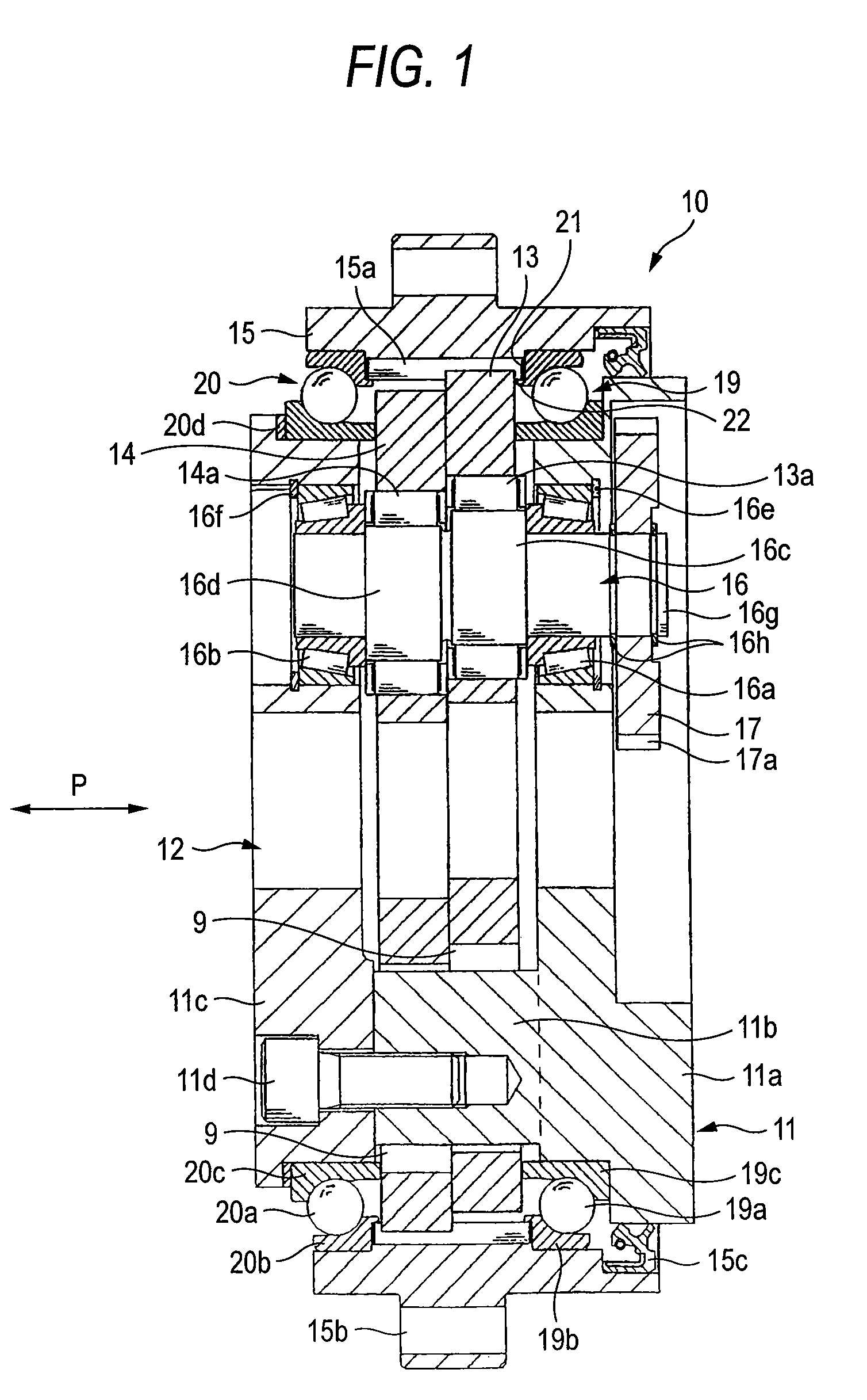
[0025]A preferred embodiment for implementing the present invention will be described with reference to the drawings. FIG. 1 is a side cross-sectional view showing an eccentrically oscillating gear device according to an embodiment of the present invention. FIG. 2 is a side cross-sectional view of the main part of FIG. 1. FIG. 3 is a partial front view showing the relative positional relationship between a receiving portion provided to the outer race side surface of a main bearing of FIG. 2 and pins.

[0026]The eccentrically oscillating gear device 10 shown in FIG. 1 is equipped with an internal gear 15 having plural pin grooves formed in the inner peripheral portion (see FIG. 4) and plural pins (internal teeth) 15a disposed in the respective grooves, a carrier 11 which is relatively rotatable to the internal gear 15, a pair of main bearings 19, 20 comprising radial ball bearings disposed between the outer periphery of the carrier 11 and the inner periphery of the internal gear 15, pl...


PUM


Abstract

The eccentrically oscillating gear device is equipped with an internal gear (15) having internal gear pins (15a), a carrier (11) rotating relative to the internal gear, a pair of bearings (19, 20) that have a rolling element and a ring body for supporting the rolling element, a crank shaft supported by the carrier so as to be freely rotatable and external gears (13, 14) that are equipped with external teeth having a trochoid tooth profile whose tooth top portions are cut out, and disposed between the pair of bearings. The outer peripheries of the external gears are engaged with the internal gear pins and fitted to the crank portion of the crank shaft. The eccentrically oscillating gear device is designed so that the external gear makes an eccentrically oscillating motion by rotation of the crank shaft and the rotational output is taken out from the internal gear or the carrier.

Description

CROSS-REFERENCE TO RELATED APPLICATIONS[0001]This application is a Section 371 of International Application No. PCT / JP2004 / 019121, filed Dec. 21, 2004, which was published in the Japanese language on Aug. 11, 2005, under International Publication No. WO 2005 / 073595 A1, the disclosure of which is incorporated herein by reference.BACKGROUND OF THE INVENTION[0002]The present invention relates to an eccentrically oscillating gear device in which an external gear is a trochoid tooth profile and an internal gear is a pinwheel.[0003]An eccentrically oscillating gear device is used in a reducer for driving an arm member of a robot provided to a joint portion of an industrial robot, for example. The following Patent Document 1 discloses an eccentrically oscillating gear device in which an external gear comprises a peritrochoid tooth profile and an internal gear comprises a pinwheel. In this eccentrically oscillating gear device, as shown in FIGS. 4(a), (b), by cutting out the tip portions of...

Claims


Application Information

Patent Timeline
Patent Type & Authority Patents(United States)
IPC IPC(8): F16H1/32F16C33/58
CPCF16H1/32F16H1/00
Inventor FUJIMOTO, KENICHIHIBINO, TOSHIHARU
Owner NABLESCO CORP
Why Eureka
Try Eureka