

Device for moisture exchange between gas flows
a technology of gas flow and moisture exchange, which is applied in the direction of membranes, heating types, separation processes, etc., can solve the problems of large limitation of moisture exchange rate and the difficulty of achieving the effect of enhancing the exchange ra
Inactive Publication Date: 2009-10-20
AIR TO AIR SWEDEN AB
View PDF14 Cites 12 Cited by
- Summary
- Abstract
- Description
- Claims
- Application Information
AI Technical Summary
Benefits of technology
"The present invention is a device for exchanging moisture between two counter-current gas flows. The device creates more favorable flow characteristics for faster moisture exchange by forming a generally parallel and homogeneous flow of air inside the chamber where moisture exchange occurs. This is achieved by a design that includes a support and flow distributing member with flow openings that are uniformly distributed over the area. The device also includes a tapered form of end portions of the ducts that extend through the inlet space. The technical effects of the invention are increased efficiency and faster moisture exchange between gas flows."
Problems solved by technology
Even though this known device allows for exchange of moisture between the two air flows, it exhibits some problems concerning the exchange efficiency since the moisture exchange rate is limited.
This limitation in moisture exchange rate is to a large extent caused by unfavourable flow characteristics of the two air flows.
Method used
View moreImage
Smart ImageViewing Examples

Examples
first embodiment
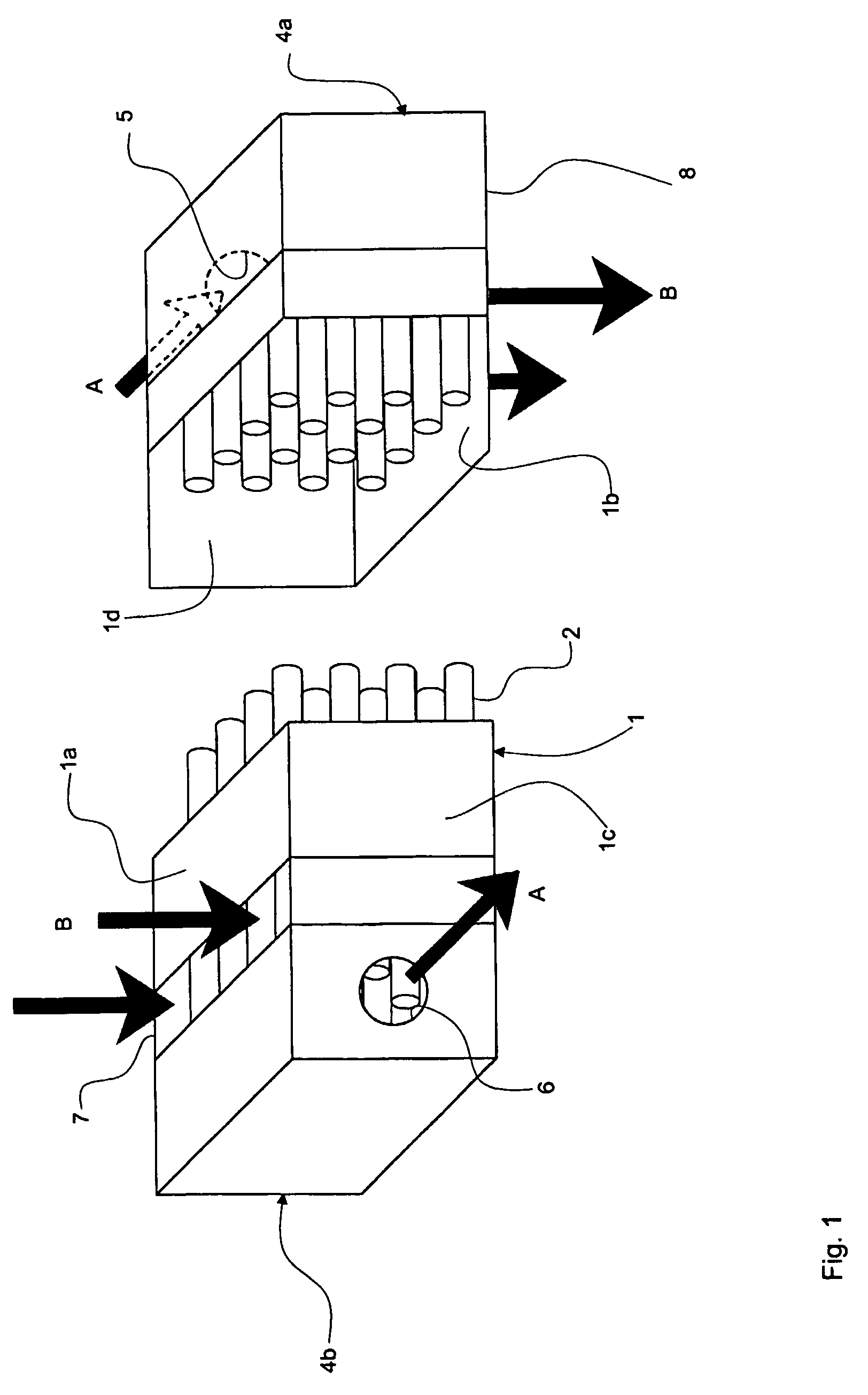
[0013]FIG. 1 is a schematic drawing in perspective with parts broken away of the device according to the invention.
second embodiment
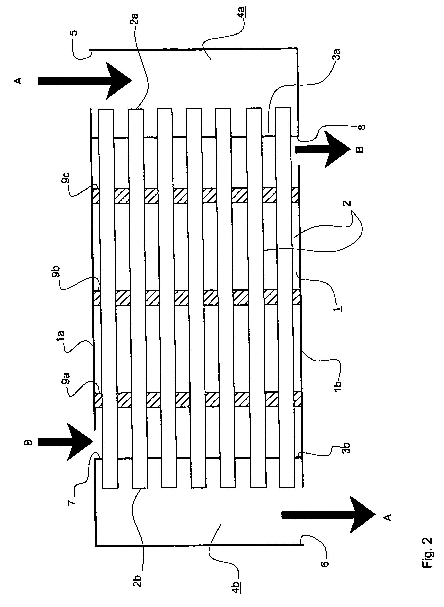
[0014]FIG. 2 is a schematic side elevation cut through a vertical longitudinal plane of a device according to a
third embodiment
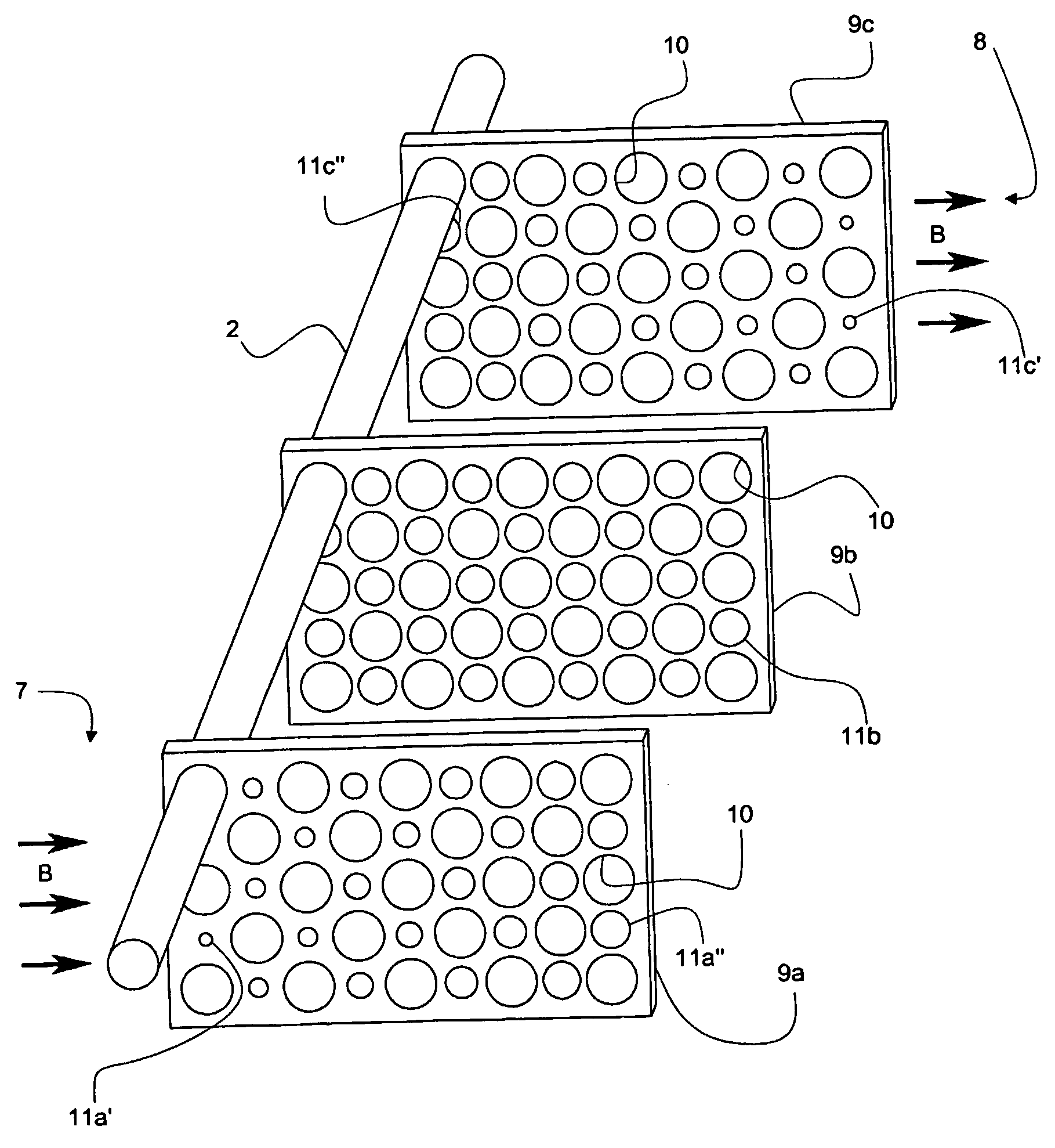
[0015]FIG. 3 is a schematic drawing in perspective of the interior of a device according to the invention.
Login to View More PUM
| Property | Measurement | Unit |
|---|---|---|
| permeability | aaaaa | aaaaa |
| sizes | aaaaa | aaaaa |
| area | aaaaa | aaaaa |
Abstract
Device for exchange of moisture, between at least two counter-current gas flows (A, B), comprising a generally closed chamber (1, 101) having an inlet (7, 107) and an outlet (8, 108) for a first gas flow (B), such that the first gas flow flows in a first direction from the inlet to the outlet inside the chamber; and at least one duct (2, 102), which extends inside the chamber, generally in parallel with the first direction, which duct (2, 102) is arranged to conduct a second fluid flow (A) in an opposite direction to the first direction and which duct (2, 102) comprises a duct wall material with high permeability to water. In order to enhance the efficiency of the moisture exchange the device comprises an inlet space for the gas flow B, which inlet space is arranged in the central chamber (1, 101), between the inlet (7, 107) and a first support and flow distributing member (9a, 109a) arranged inside the chamber (1, 101) between the inlet opening (7, 107) and the outlet opening (8, 108), and means for uniform distribution of the gas inside the inlet space for providing a generally parallel and uniform first fluid flow (B) inside the chamber.
Description
FIELD OF THE INVENTION[0001]The present invention relates to a device for exchange of moisture, between at least two counter-current gas flows, comprising a generally closed chamber having an inlet and an outlet for a first gas flow, such that the first fluid flow flows in a first direction from the inlet to the outlet inside the chamber; and at least one duct, which extends inside the chamber, generally in parallel with the first direction, which duct is arranged to conduct a second gas flow in an opposite direction to the first direction and which duct comprise a duct wall material with high permeability to water.[0002]The device is particularly useful for exchanging moisture from a first air flow to a second air flow, in order to desiccate the first air flow. The device may find various different applications e.g. in the fields of stationary and mobile air conditioning, refrigeration and heat exchanging.PRIOR ART[0003]Such devices are used e.g. for desiccating inlet air to a buil...
Claims
Login to View More Application Information
Patent Timeline
 Patent Type & AuthorityPatents(United States)
IPC IPC(8): B01D53/22F24F3/14F28F9/013B01D53/26B01D63/06F24F3/147F28D7/16F28D21/00
CPCB01D53/268B01D63/06F24F3/147F28D7/16F28F9/0131F28D21/0015B01D2319/04B01D2313/08B01D2313/38B01D2313/221B01D63/069
InventorSIVERKLEV, JOHAN
OwnerAIR TO AIR SWEDEN AB