Transportable hydro-electric system

a technology of hydro-electric system and transportable structure, which is applied in the direction of electric generator control, renewable energy generation, greenhouse gas reduction, etc., can solve the problems of low power return, limiting factors, and low power return of systems, and achieve the effect of maximizing the inherent pressure of water flow

Inactive Publication Date: 2009-10-20
SRYBNIK SIMON +1
View PDF30 Cites 25 Cited by
  • Summary
  • Abstract
  • Description
  • Claims
  • Application Information

AI Technical Summary

Problems solved by technology

These systems were never popular because of the low return of power based on lack of sufficient water pressure to run the generation equipment.
In addition, with the high cost of construction of facilities in many areas, the amount of electrical return that the system provides is also a limiting factor.
The cost of assembly and material transport many times makes the possible site impractical, thus scrapping the possibility of use due to poor return of investment.
However, in this system, the compressive force applied to the water flow is limited to the internal forces applied by the confinement of that chamber making the system still not fully maximized.
Again, the initial pressure is not optimized in any way.
Because of the small amount of power generated by this system, it again is highly impractical for use in generation of power for external applications.

Method used


Image

  • Transportable hydro-electric system
  • Transportable hydro-electric system
  • Transportable hydro-electric system

Examples


Embodiment Construction

[0022]The preferred embodiments of the instant invention are described in terms of the FIGS. 1-8. Identical elements contained in various figures are designated with the same numeral in each figure.

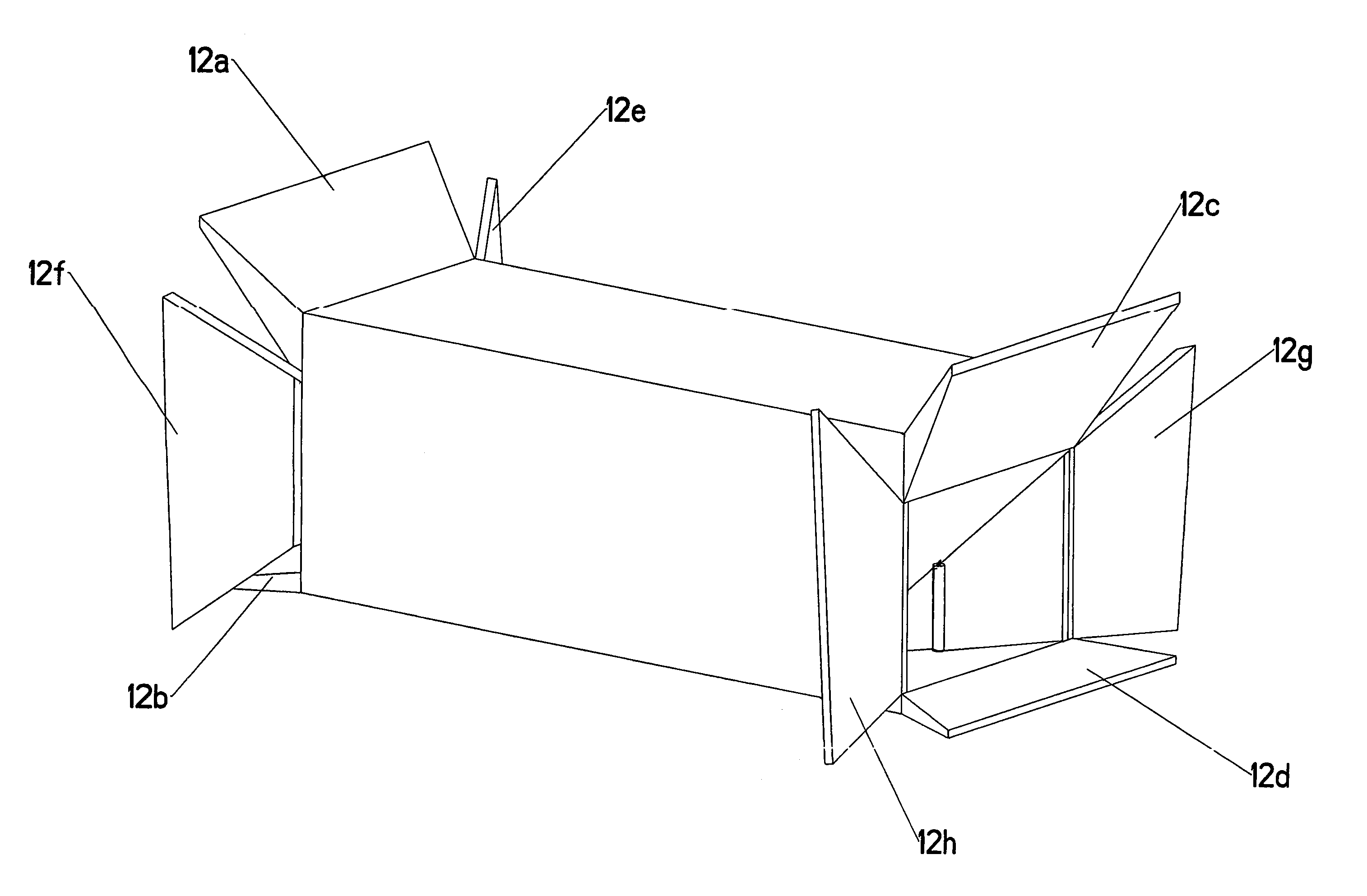
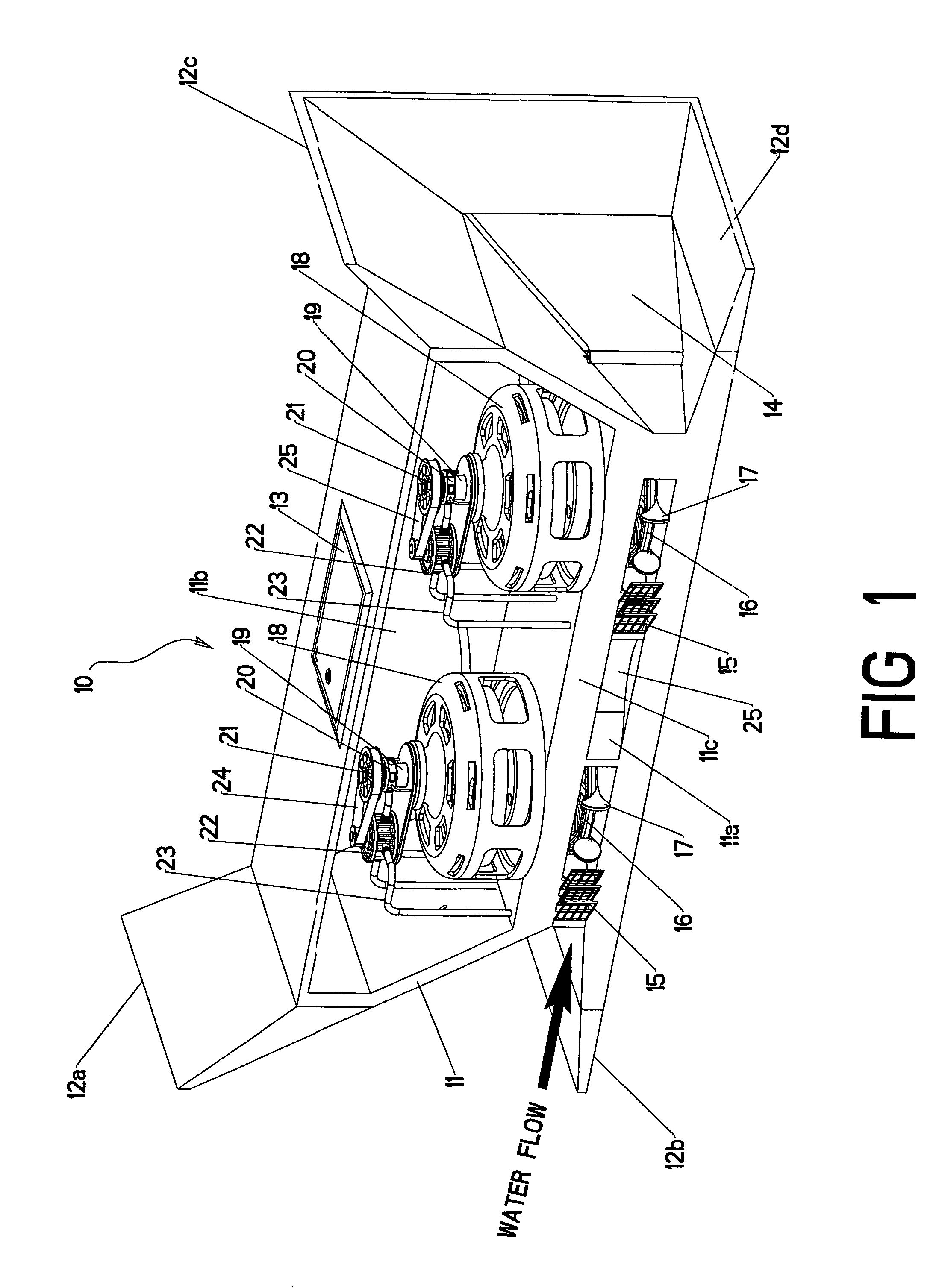
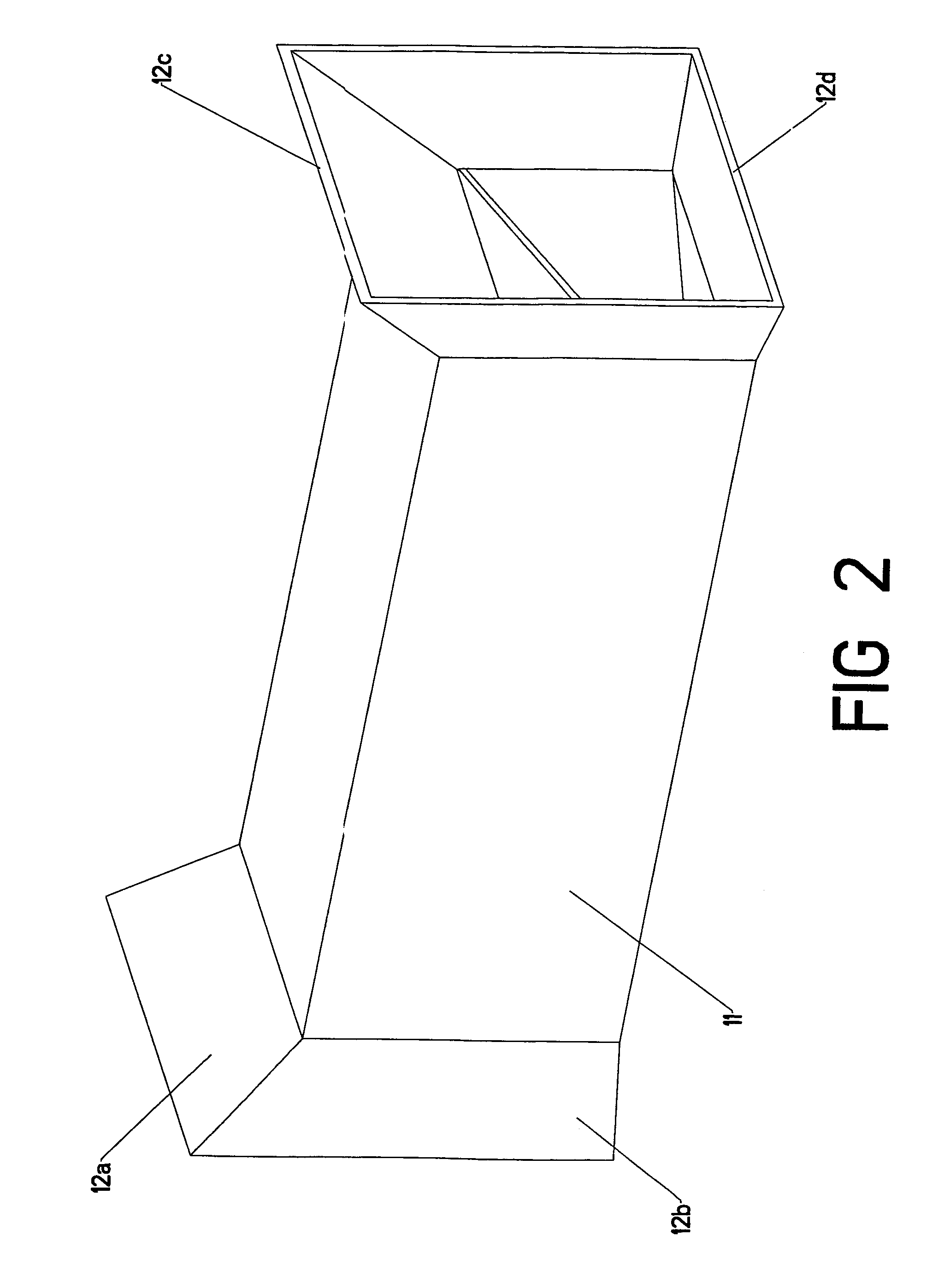
[0023]Referring now to FIG. 1, the overall design of the transportable hydroelectric power generating system 10 is shown. The hydroelectric power generating system comprises a housing 11 which includes a main body which is open to the flowing water shown by 11a and a sealed portion 11b which allows for the generators and pumps to operate in atmospheric conditions and not in an aqueous environment. This housing, depicted in FIG. 2, may be made of any suitable material which is capable of rendering a protective environment for the system 10, and may be selected from metals, concrete, fiberglass, engineering plastics or other materials as known to those of ordinary skill in the art. The housing includes flanges 12a, 12b, 12c and 12d which are water channeling features. A trap door 13 is also...


PUM


Abstract

The invention is a transportable hydroelectric power generating system which is capable of being fully or partially assembled in a factory setting and then transported to a water stream. The system includes water channeling features which enhance the pressure within the system that the water exerts and a secondary pump feature which serves to further supply pressurized water to the impellers on the water wheels. Thus marginal streams may become power generating sites.

Description

BACKGROUND OF THE INVENTION[0001]The present invention relates to a hydroelectric power generating system for maximizing the use of water currents incident upon a set or series of wheels connected to an electric current generating system. In addition, the invention addresses the need to generate power from bodies of water heretofore incapable of being utilized as hydroelectric generating sources because the flow characteristics of the stream were considered below the threshold of desired pressures for use in generating systems.[0002]With the increased costs of electrical power generation from fossil fuels, the desire to generate energy without increasing pollution and the need for more power in all areas of consumption, it has become more important to find ways to generate electricity that use existing natural resources. This enhances the ability to add power sources in an economical fashion and to permit new avenues of supply to an increasing population and increasing demand withou...

Claims


Application Information

Patent Timeline
Patent Type & Authority Patents(United States)
IPC IPC(8): F03B13/00F01D15/10H02K7/18F02C6/00
CPCF03B1/02F03B1/04F03B13/10F03B17/063F05B2240/12F05B2240/123Y02E10/28F05B2240/14F05B2250/5011F05B2250/80Y02E10/22Y02E10/223F05B2240/133Y02E10/20Y02E10/30
Inventor SRYBNIK, SIMONSRYBNIK, LOUIS
Owner SRYBNIK SIMON
Why Eureka
Try Eureka