Systems for highly efficient solar power conversion
What is AI technical title?
AI technical title is built by Patsnap AI team. It summarizes the technical point description of the patent document.
a solar power and conversion system technology, applied in the field of solar power, can solve the problems of greater energy harvesting and better cost, and achieve the effects of high power conversion efficiency, high efficiency dc-dc conversion, and high total energy harvesting from the overall system
Active Publication Date: 2009-10-20
AMPT
View PDF203 Cites 358 Cited by
Summary
Abstract
Description
Claims
Application Information
AI Technical Summary
This helps you quickly interpret patents by identifying the three key elements:
Problems solved by technology
Method used
Benefits of technology
Benefits of technology
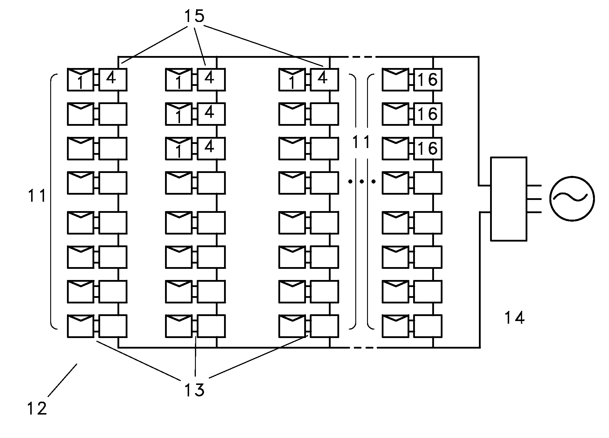
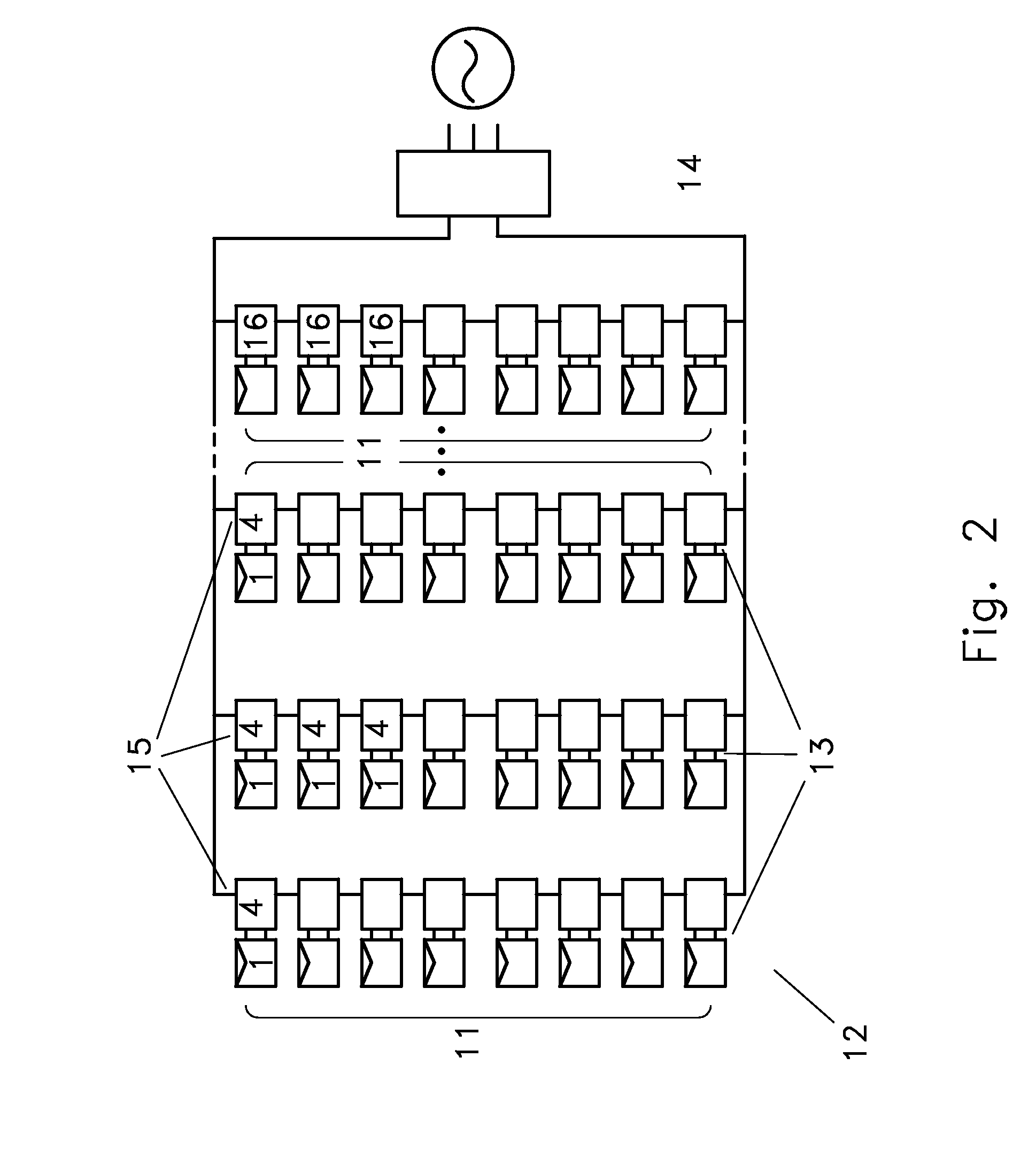
[0020]As to the MPPT aspect, in embodiments, this invention may permit each and every panel to individually produce its maximum power thereby harvesting more total energy from the overall system. Systems may be configured with an MPP circuit and a highly efficient power conversion circuit on each panel. These circuits may be made as simple inexpensive circuitry to perhaps perform several functions. First, MPPT can be achieved and this circuit may be designed to extract the maximum power available from each and every panel. Second, it may be configured to transform to an impedance or voltage which naturally combines with the other panels in a series string. This circuit may also be configured for parallel connected panels or even for single cells or strings within a panel. Embodiments may be configured so that the output may be a higher voltage output (for example, 400V). Additionally, configurations may allow for an easy to administer overvoltage or other protection, perhaps even with or without feedback elements that control the system to avoid an overvoltage or other condition.
[0021]The addition of individual MPP circuitry to act upon a panel may even be configured so as to provide an inexpensive addition and, in some embodiments, may replace the need for the same function in the power converter. The circuitry may be added to the PV panels and may not need to be repeated in a grid-tied inverter. This may thus result in the same total circuitry with significant advantage. In embodiments there may actually be several small MPP converters replacing one large one. Importantly from some perspectives, this can be achieved through conversion circuitry and control that can provide highly efficient DC-DC conversion even with 97%, 98%, 99.2%, or essentially even wire transmission loss efficiencies which can be considered the highest possible while also achieving MPPT operation for the panels. This may result in even greater energy harvesting and better cost result.
Problems solved by technology
This may result in even greater energy harvesting and better cost result.
Method used
Image
Click on the blue label to locate the original text in one second.
Reading with bidirectional positioning of images and text.
Examples
Embodiment Construction
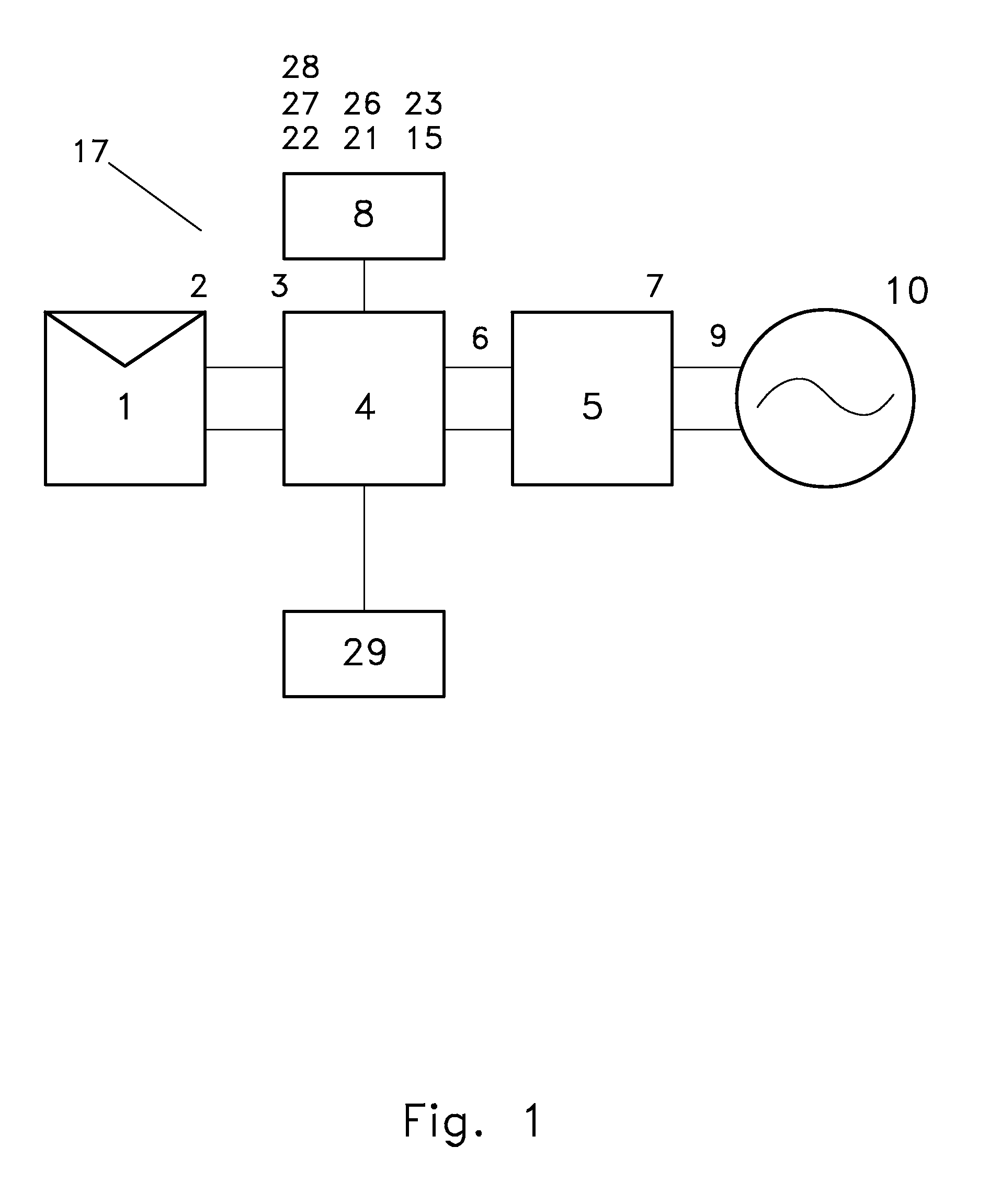
[0032]As mentioned above, the invention discloses a variety of aspects that may be considered independently or in combination with others. Initial understanding begins with the fact that one embodiment of a power conditioner according to the present invention may provide an alternative process converter, a dual mode photovoltaic converter, a very high efficiency photovoltaic converter, or a multimodal photovoltaic converter, all perhaps with the inclusion of maximum power point tracking (MPP or MPPT) aspects. Such elements may present alternative process conversion, dual mode photovoltaic conversion, a highly efficient method of solar energy power conversion, etc. Embodiments may include operational boundaries such as for output voltage, output current, and perhaps even, output power. Each of these should be understood from a general sense as well as through embodiments that display initial applications for implementation. Some initial benefits of each of these aspects are discussed...
PUM
Abstract
A high efficiency photovoltaic DC-DC converter achieves solar power conversion from high voltage, highly varying photovoltaic power sources to harvest maximum power from a solar source or strings of panels for DC or AC use, perhaps for transfer to a power grid at high power levels with coordinated control possible for various elements. Photovoltaic DC-DC converters can achieve efficiencies in conversion that are extraordinarily high compared to traditional through substantially power isomorphic photovoltaic DC-DC power conversion capability that can achieve 97%, 98%, 99.2% efficiency, or even only wire transmission losses. Switchmode impedance or voltage conversion circuit embodiments may have pairs of photovoltaic power interrupt switch elements and pairs of photovoltaic power shunt switch elements to first increase voltage and then decrease voltage as part of the desired photovoltaic DC-DC power conversion.
Description
[0001]This application is a continuation-in-part of prior International Application No. PCT / US2008 / 080794, filed Oct. 22, 2008, which claims benefit of and priority to U.S. Provisional Application No. 60 / 982,053, filed Oct. 23, 2007, and U.S. Provisional Application No. 60 / 986,979, filed Nov. 9, 2007; this application is a continuation-in-part of prior International Application No. PCT / US2008 / 070506, filed Jul. 18, 2008, which is a continuation-in-part of prior International Application No. PCT / US2008 / 060345, filed Apr. 15, 2008, and which is a continuation-in-part of prior International Application No. PCT / US2008 / 057105, filed Mar. 14, 2008, and which claims benefit of and priority to U.S. Provisional Application No. 60 / 980,157, filed Oct. 15, 2007, U.S. Provisional Application No. 60 / 982,053, filed Oct. 23, 2007, and U.S. Provisional Application No. 60 / 986,979, filed Nov. 9, 2007; this application is a continuation-in-part of prior International Application No. PCT / US2008 / 060345, ...
Claims
Application Information
Patent Timeline
Application Date:The date an application was filed.
Publication Date:The date a patent or application was officially published.
First Publication Date:The earliest publication date of a patent with the same application number.
Issue Date:Publication date of the patent grant document.
PCT Entry Date:The Entry date of PCT National Phase.
Estimated Expiry Date:The statutory expiry date of a patent right according to the Patent Law, and it is the longest term of protection that the patent right can achieve without the termination of the patent right due to other reasons(Term extension factor has been taken into account ).
Invalid Date:Actual expiry date is based on effective date or publication date of legal transaction data of invalid patent.

