System and method for dynamically controlling operation of rheometric instruments

a dynamic control and rheological technology, applied in the field of rheological instrument operation, can solve the problems of inability to alter the instrument programming to achieve this level of customization, detract from the effect of alterations to the user interface, and material rheological properties may be displayed, etc., to achieve the effect of convenient programming and configuration

Active Publication Date: 2009-10-20
WATERS TECH CORP
View PDF10 Cites 10 Cited by
  • Summary
  • Abstract
  • Description
  • Claims
  • Application Information

AI Technical Summary

Benefits of technology

[0016]The present invention relates to a method and system for creating tests to be performed on a rheometer instrument using a robust, programmable interface. The interface enables users to assemble pre-configured test procedures or to custom-build tests using a scripting programming language. Custom-built tests can be stored for later use or inclusion within other tests. Forms are dynamically generated according to the type of test that is created and the parameters associated with the test, and forms also can be customized to prompt users only for specified parameter values. The graphical user interface includes a drag-and-drop, icon-based visual system to facilitate easy programming and configuration, in addition to tree views illustrating the hierarchical nature of test design and preparation.

Problems solved by technology

Such materials may exhibit rheological properties that are not easily described through classical fluid mechanics and elasticity.
In conventional rheometer systems in which the testing procedure is completely integrated with the instrument, it might not be possible to alter the instrument programming to achieve this level of customization without modifications to the instrument firmware and the controlling software.
Such alterations to the user interface may detract from performing other tests using the instrument, and the information required to make these modifications is generally not available to the end user.
Accordingly, the pre-configurability of conventional rheometer instruments is disadvantageous in situations where a scientist wishes to design a customized testing pattern.

Method used


Image

  • System and method for dynamically controlling operation of rheometric instruments
  • System and method for dynamically controlling operation of rheometric instruments
  • System and method for dynamically controlling operation of rheometric instruments

Examples


example

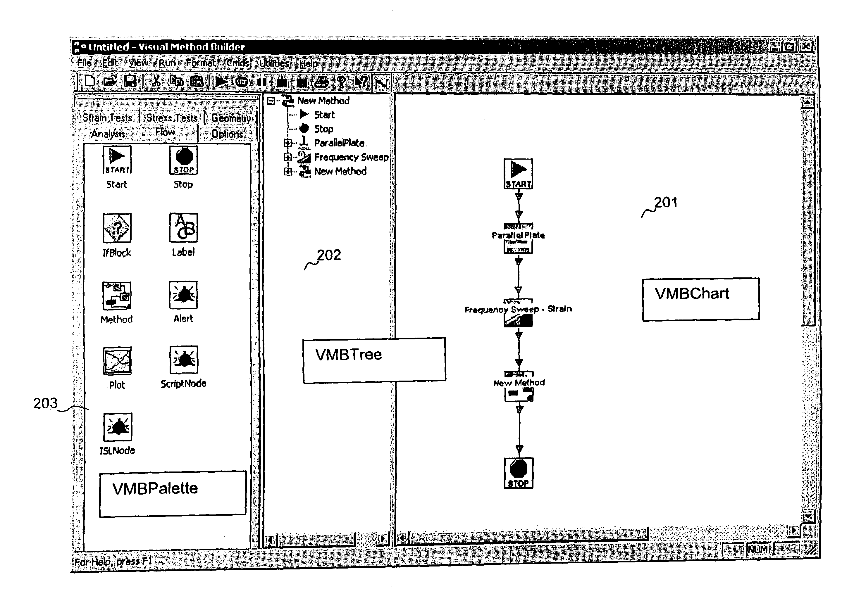
[0097]FIGS. 11 and 12 illustrate an example of a method that is generated in the instrument interface for operating an instrument. As can be seen in FIG. 11, the “Start” icon is automatically placed within the VMB chart to define a reference point for building a method. The next icon, denoted “Cone Plate,” is selected from the “Geometry” category in the VMB Palette on the left, and is utilized for defining a test geometry. Particularly, the “Cone Plate” is related to the geometry of the sample. Once the “Cone Plate” icon is dragged-and-dropped into the chart, a “flow wire” is created between the two icons to indicate the directional flow to this node. By double-clicking on the “Cone Plate” icon, a form is displayed for the user to provide parameter values.

[0098]The chart next includes a “Go To Gap” icon, which relates to moving the platform, or stage, that holds the geometry to a predetermined position after a sample has been loaded. Thus, upon execution of a script in the instrumen...


PUM

PropertyMeasurementUnit
rheologyaaaaaaaaaa
rheological parametersaaaaaaaaaa
rheological propertiesaaaaaaaaaa

Abstract

System and methods are described for dynamically controlling operation of a rheometer. A program is created on a programming interface for executing a test upon a sample in a rheometer by receiving user selections of a plurality of nodes and connections of each node to another node according to directional connection indicators. Nodes indicate steps for performing a test upon a sample or configuring a rheometer for performing a test upon a sample. Scripts are created for generating a sequence of instructions to the rheometer. The scripts include instructions for performing steps indicated by each of the selected nodes and in accordance with the directional connection indicators. Low-level instructions are downloaded from the scripts for execution in the rheometer, and drivers in the rheometer are instructed for performing the downloaded instructions.

Description

[0001]This application claims the benefit of U.S. Provisional Application No. 60 / 454,346, filed Mar. 14, 2003, which is herein incorporated by reference in its entirety.BACKGROUND OF THE INVENTION[0002]1. Field of the Invention[0003]The present invention relates to operation of rheometric instruments, and more particularly, to graphical and programming interface systems and methods for dynamically controlling operation of rheometric instruments.[0004]2. Background Information[0005]The term “rheology” relates to the study of the deformation and flow of matter. Rheological testing was originally associated with the examination of properties and behavior of materials such as asphalt, lubricants, paints, plastics, rubber, and fluids. Such materials may exhibit rheological properties that are not easily described through classical fluid mechanics and elasticity. Developers of other products, including many that are associated with general consumer use, are also studying the rheological a...

Claims


Application Information

Patent Timeline
Patent Type & Authority Patents(United States)
IPC IPC(8): G06F3/00G01N11/00G06F9/44G06F9/445G06F19/00
CPCG06F8/34G01N2011/0006
Inventor GREHLINGER, PETER MARKGARRITANO, RONALD F.BERTING, JOHN P.
Owner WATERS TECH CORP
Why Eureka
Try Eureka