Interlocking highway structure

a highway structure and interlocking technology, applied in the direction of roads, roadway safety arrangements, constructions, etc., can solve the problems of deflection of each section, achieve the effect of facilitating alignment and stability of the entire system, facilitating separation and improving crash performan

Active Publication Date: 2009-10-27
EASI SET INDS
View PDF17 Cites 9 Cited by
  • Summary
  • Abstract
  • Description
  • Claims
  • Application Information

AI Technical Summary

Benefits of technology

[0006]It is an object of the present invention to provide an inexpensive highway crash barrier system consisting of rigid sections which are joinable together, which are easily separated from each other, and which provide improved crash performance.
[0007]A further object of the present invention is to provide an improved system of interlocking sections for a highway crash barrier system in which the sections engage one another in a simple but mechanically sound manner to facilitate alignment and stability of the entire system without encumbering it with expensive and complex coupling devices. The present invention includes longer sections of connecting plate area than prior designs of JJ Hooks® which reduces the rotational moment of the barrier system segments in both the free-standing and the bolted down configurations, and integral deflection limiting “stops” which provide improvement in barrier deflection during impact.
[0008]According to the invention, an interlocking barrier system includes a plurality of rigid upright sections that can be joined together end-to-end using a “J” shaped connection member. The connection member preferably is embedded in a recessed cavity in each end of each section and has an outwardly projected hook. The connection member, as well as its associated hook and an outwardly projected receptacle flange, ran linearly along a line extending from the top to the bottom of each end of each section (e.g., 24″) a distance which almost equals the height of each section. A plurality of bars (e.g. rebar) are welded or otherwise joined to the connection member and extend into the concrete section a distance that assures steel shear at pullout. In one embodiment, the rebar may extend end-to-end in the barrier structure. In another embodiment, the rebar do not traverse end-to-end distance of the section, and may extend two feet or more. This configuration eliminates or reduces the rotational forces imparted by a collision at one end of the section being imparted at the other end, thus making the interlocking structure more compliant with newer crash test safety requirements.
[0009]Further, the addition of deflection limitation stops positioned at the forward lower corners of each section prevents spalling and damage at the corners and limits the deflection of each section from crash impact. The reduction in spalling of the leading edge of the barrier segments at the base significantly reduces deflection of the chain of barrier segments upon vehicle impact which increases the safety margin for workers behind the precast barriers.
[0010]The combination of the longer connection length and deflection limitation blocks enhances the stiffness of the system when free-standing, bolted, or pinned down, resulting in a significant reduction in the rotational moment providing less ride down acceleration and vaulting for the impacted vehicle and its occupants.

Problems solved by technology

Further, the addition of deflection limitation stops positioned at the forward lower corners of each section prevents spalling and damage at the corners and limits the deflection of each section from crash impact.

Method used


Image

  • Interlocking highway structure
  • Interlocking highway structure
  • Interlocking highway structure

Examples


Embodiment Construction

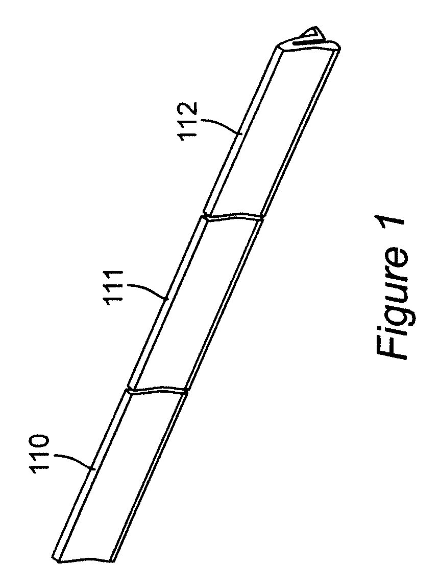
[0015]In FIG. 1 of the drawings, for exemplary purposes, three rigid upright sections 110, 111, and 112 linked end-to-end in alignment to form a highway barrier system. An unlimited number of sections can be linked together and positioned to follow the path of a roadway (or perimeter of a building in the case of building protection application) in the practice of the invention. Further, the outer shape and length of the upright sections 110, 111, and 112 can vary for different applications. The invention can be used in roadwork as well as security and other applications.

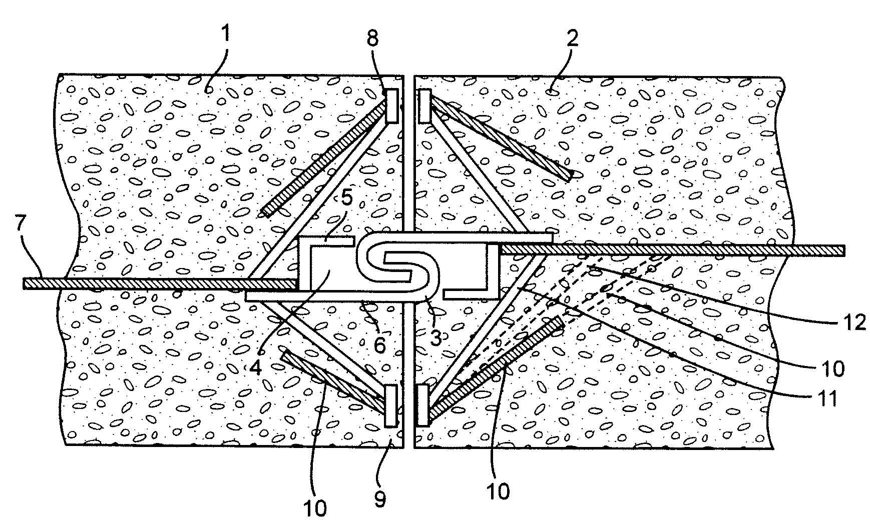
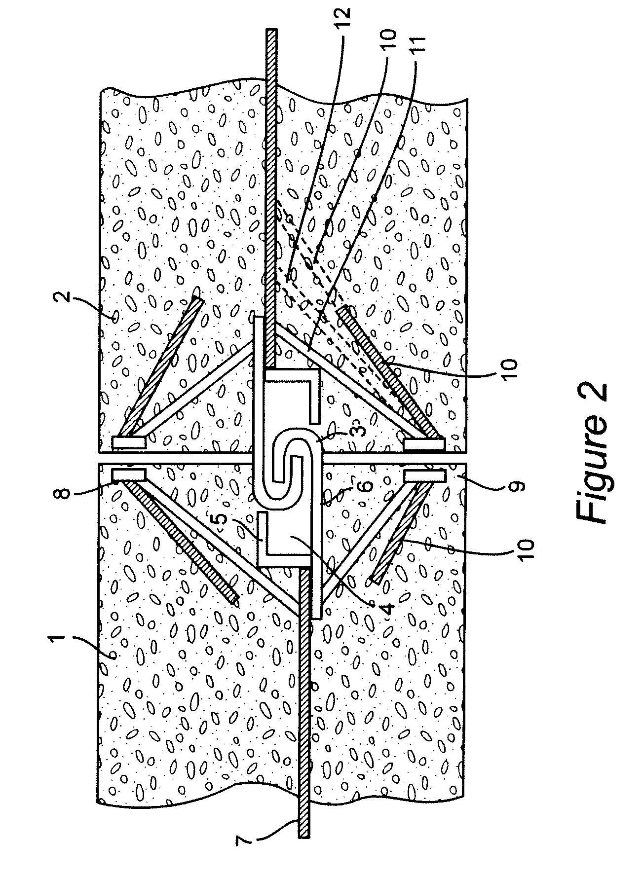
[0016]FIG. 2 of the drawings illustrates in detail the actual interlocking structure whereby two rigid upright sections 1 and 2 of the barrier system are maintained in alignment with one another. As illustrated, the hook member 3 in the cavity 4 of the end of each upright section projects outward from the section. A recessed flanged member 5 is attached to the connection member. Metallic welded bars 7 (only one bar i...


PUM


Abstract

A highway crash barrier structure with an improved interlocking system includes a plurality of rigid sections disposed end-to-end in interlocking relationship with one another. The ends of each rigid upright section are provided with a reshaped JJ Hooks® connection. Each hook member has an extending vertical lip which is bent into a “J” shaped cross-section to engage a similar lip on the hook member of the adjacent section such that lateral movement of the respective sections is prevented. However, the respective sections of the system can be easily placed or removed by vertically displacing them. In addition, the interlocking plates at each end of the upright sections are vertically lengthened while the number of bars welded to the plate is increased to reduce the rotational moment of the sections and increase shear transfer between adjacent sections. Furthermore, connections include deflection limitation stops located at the lower part of each end of each upright section which prevents spalling and decreases deflection during a crash. The deflection stops can be positioned wholly within the rigid sections or can protrude partway out the bottom of the sections for particular applications.

Description

FIELD OF THE INVENTION[0001]The invention generally relates to a highway crash barrier system able to address current requirements for improving the crash performance of precast concrete barriers. The barrier system comprises a plurality of rigid sections disposed end-to-end in interlocking relationship with one another. The end of each section has a cavity and is provided with embedded interlocks that join with one another to hold the sections together. Individual sections can be removed or replaced without disrupting the remainder of the barrier system while maintaining proper alignment. The invention has application both in road and in highway environments, as well as being used for protection and security at airports, government buildings, and the like.BACKGROUND OF THE INVENTION[0002]In recent years, for controlling the flow of traffic, various barrier systems consisting of large sections of precast concrete have been used along highways. The sections can be hoisted into place ...

Claims


Application Information

Patent Timeline
Patent Type & Authority Patents(United States)
IPC IPC(8): E01F15/02E01F9/594E01F9/646
CPCE01F15/088E01F15/083
Inventor SMITH, RODNEY
Owner EASI SET INDS
Why Eureka
Try Eureka