
Vehicle air system and method with forced purging

a technology of compressed air and vehicle, which is applied in the direction of drying machines, lighting and heating equipment, separation processes, etc., can solve the problems of adding cost and space requirements to the vehicl

Active Publication Date: 2009-10-27
BENDIX COMML VEHICLE SYST LLC
View PDF13 Cites 16 Cited by
  • Summary
  • Abstract
  • Description
  • Claims
  • Application Information

AI Technical Summary

Problems solved by technology

If a long charge time is needed to maintain the brake system, a second dryer is used, adding cost and space requirements on the vehicle.

Method used


Image

  • Vehicle air system and method with forced purging
  • Vehicle air system and method with forced purging
  • Vehicle air system and method with forced purging

Examples


Embodiment Construction

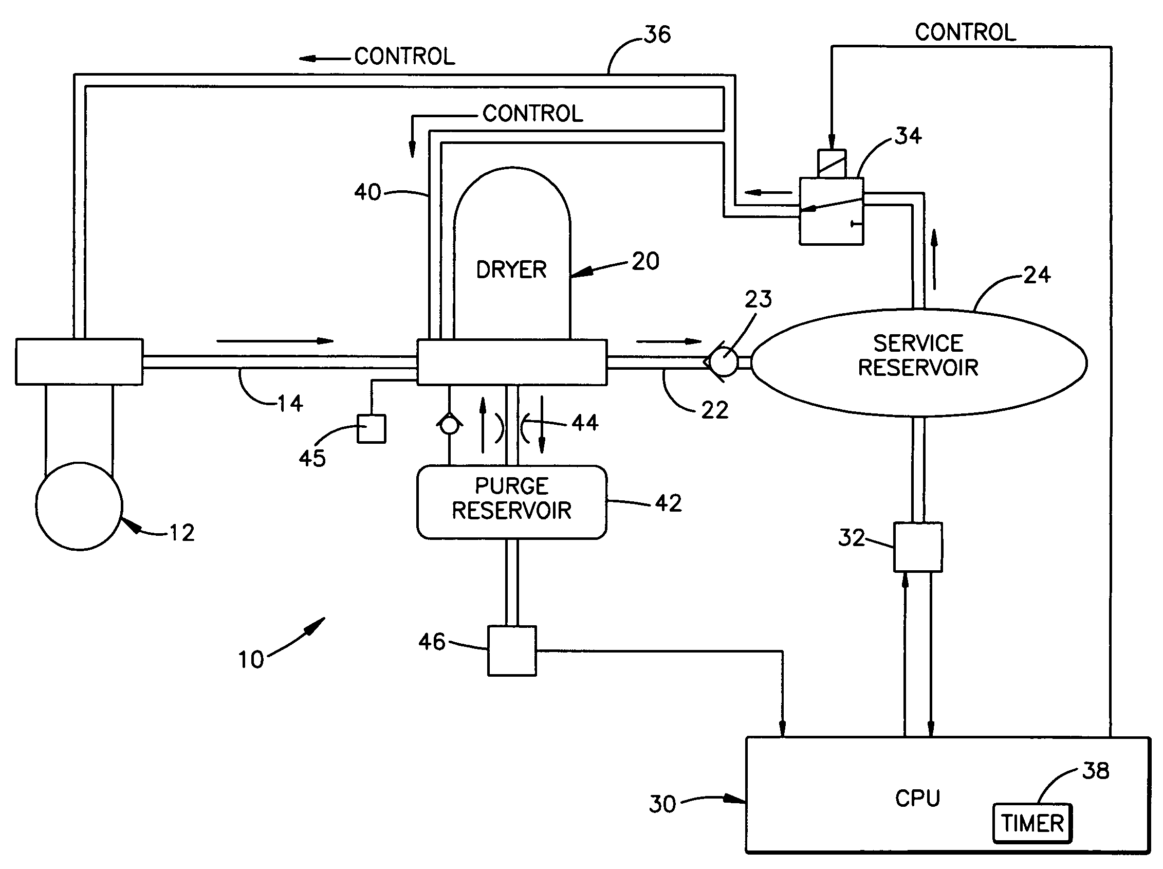
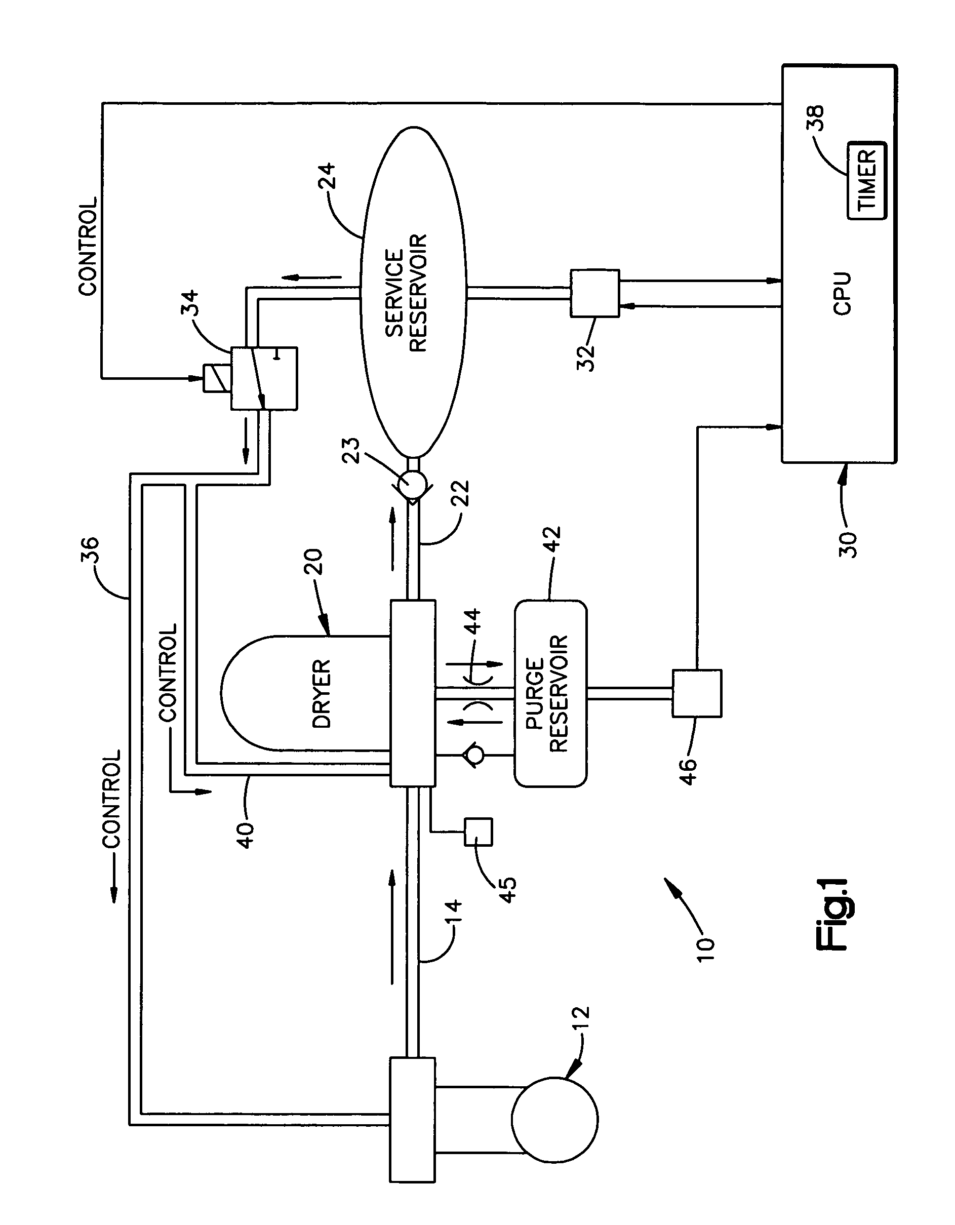
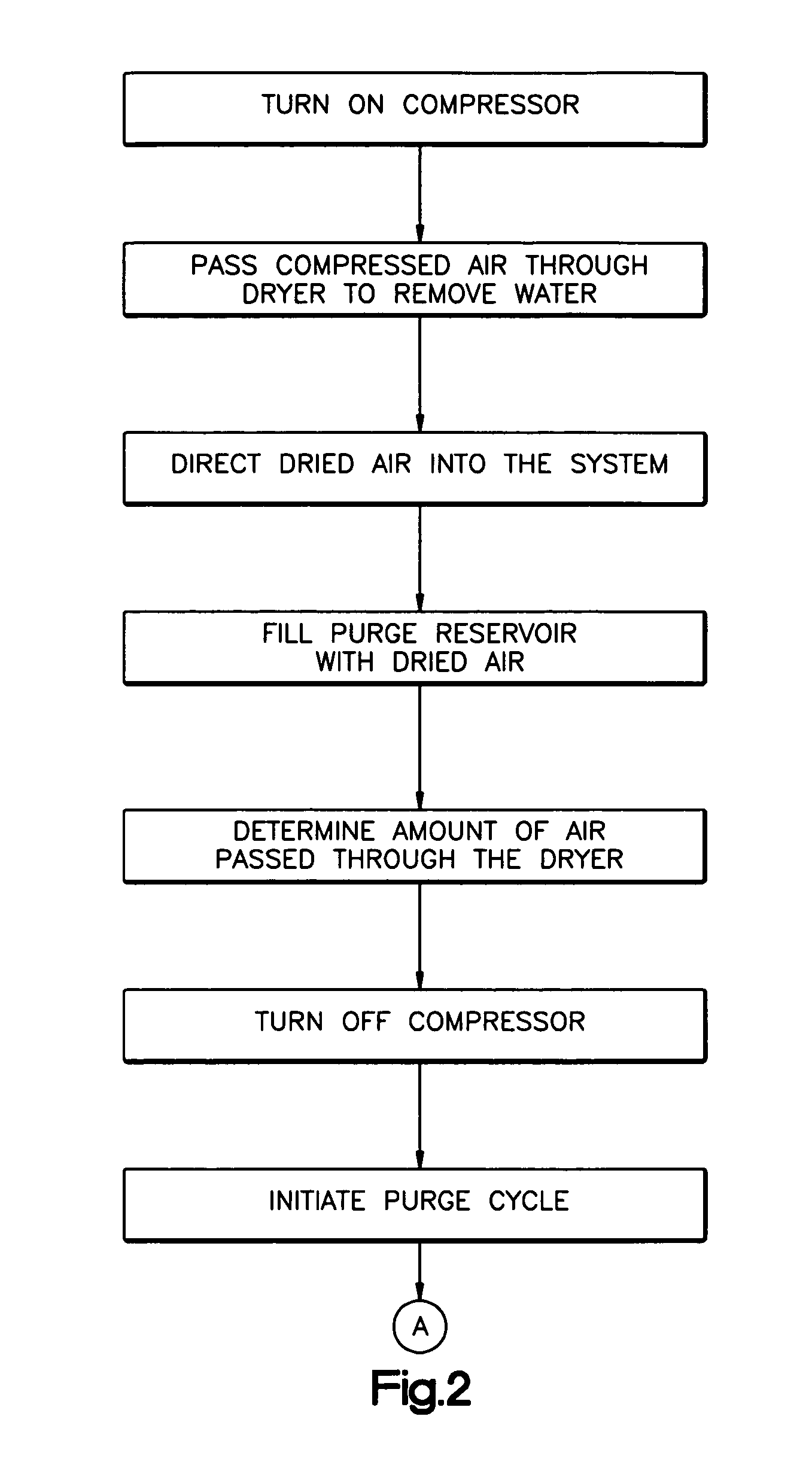
[0011]The present invention relates to a vehicle compressed air system. The invention is applicable to systems of varying constructions. As representative of the invention, FIGS. 1-3 illustrate a system 10 and corresponding method that illustrate aspects of the invention.

[0012]The system 10 includes a compressor 12 for compressing ambient air. The output of the compressor 12 is directed over a line 14 to an air dryer 20. The air dryer 20 is operative to remove water from the compressed air, for example, by use of a desiccant. The output of the air dryer 20 is directed over a line 22 to one or more service reservoirs indicated at 24 for supplying air to the devices of the system 10, such as brake actuators. A check valve 23 presents reverse flow from reservoirs to the air dryer 20.

[0013]Operation of the compressor 12 is controlled by a CPU or controller 30. The CPU 30 receives an input from a pressure sensor 32 that senses pressure in the service reservoir 24. When the sensed pressur...


PUM

PropertyMeasurementUnit
pressureaaaaaaaaaa
pressureaaaaaaaaaa
pressureaaaaaaaaaa

Abstract

A method and apparatus provide multiple consecutive purges of an air dryer in a vehicle compressed air system. A dryer throughput sensor has an output indicative of the amount of compressed air that is passed through the dryer. In response, a CPU determines the number of purges needed to purge the dryer; and a valve is operated by the CPU to initiate multiple purges of the dryer when the compressor is unloaded.

Description

BACKGROUND OF THE INVENTION[0001]A typical vehicle compressed air system, as used for operating air brakes and other devices, for example, includes a compressor that compresses ambient air to fill one or more service reservoirs. Whenever the compressor is loaded and the system is charging (the “charge phase”), compressed air passes through an air dryer and moisture or water is collected by a desiccant in the dryer. Compressed air is also passed through the dryer to a purge reservoir that is connected to the air dryer.[0002]At the end of every charge cycle, the compressor unloads, and the system automatically purges the dryer (the “purge phase”) with a flow of air from a purge reservoir located downstream of the air dryer, through a purge orifice and through the dryer. This purge regenerates the desiccant in the air dryer. A single purge is provided, no matter how long the system had been charging, and no matter how much purging might actually be required for dryer regeneration (base...

Claims


Application Information

Patent Timeline
Patent Type & Authority Patents(United States)
IPC IPC(8): B01D46/46
CPCB60T17/004
Inventor FORNOF, WILLIAM P.REISINGER, PAUL
Owner BENDIX COMML VEHICLE SYST LLC
Learn More