Co-generation power system for supplying electricity to an air-water recovery system

a technology of air-water recovery and co-generation power system, which is applied in the direction of greenhouse gas reduction, vessel construction, separation processes, etc., can solve the problems of inability to meet the needs of basic services, inability to meet the needs of industrial and military environments, and inability to meet the needs of substantial energy demands. industrial and military environment, the effect of increasing the cost of solar power

Inactive Publication Date: 2006-11-16
ZWEBNER MICHAEL J
View PDF4 Cites 29 Cited by
  • Summary
  • Abstract
  • Description
  • Claims
  • Application Information

AI Technical Summary

Benefits of technology

[0017] In either case, a substantial amount of energy is produced/co-generated, which materially reduces the overall consumption of di

Problems solved by technology

The electrical power needs in developing countries are often inadequate to supply basic services required to both sustain life and for sanitation purposes.
Solar power, although becoming increasing more cost effective, is still inadequate to provide substantial energy demands in industrial and military environments, particularly, where the environment may shift from one remote location to another.
Thus, fixed power generating devices, e.g. solar panels, wind turbines, are impractical and otherwise inadequate because of the obvious dependency upon the natural cycles of the sun and the wind.
This shortcoming in power delivery i

Method used


Image

  • Co-generation power system for supplying electricity to an air-water recovery system
  • Co-generation power system for supplying electricity to an air-water recovery system
  • Co-generation power system for supplying electricity to an air-water recovery system

Examples


Embodiment Construction

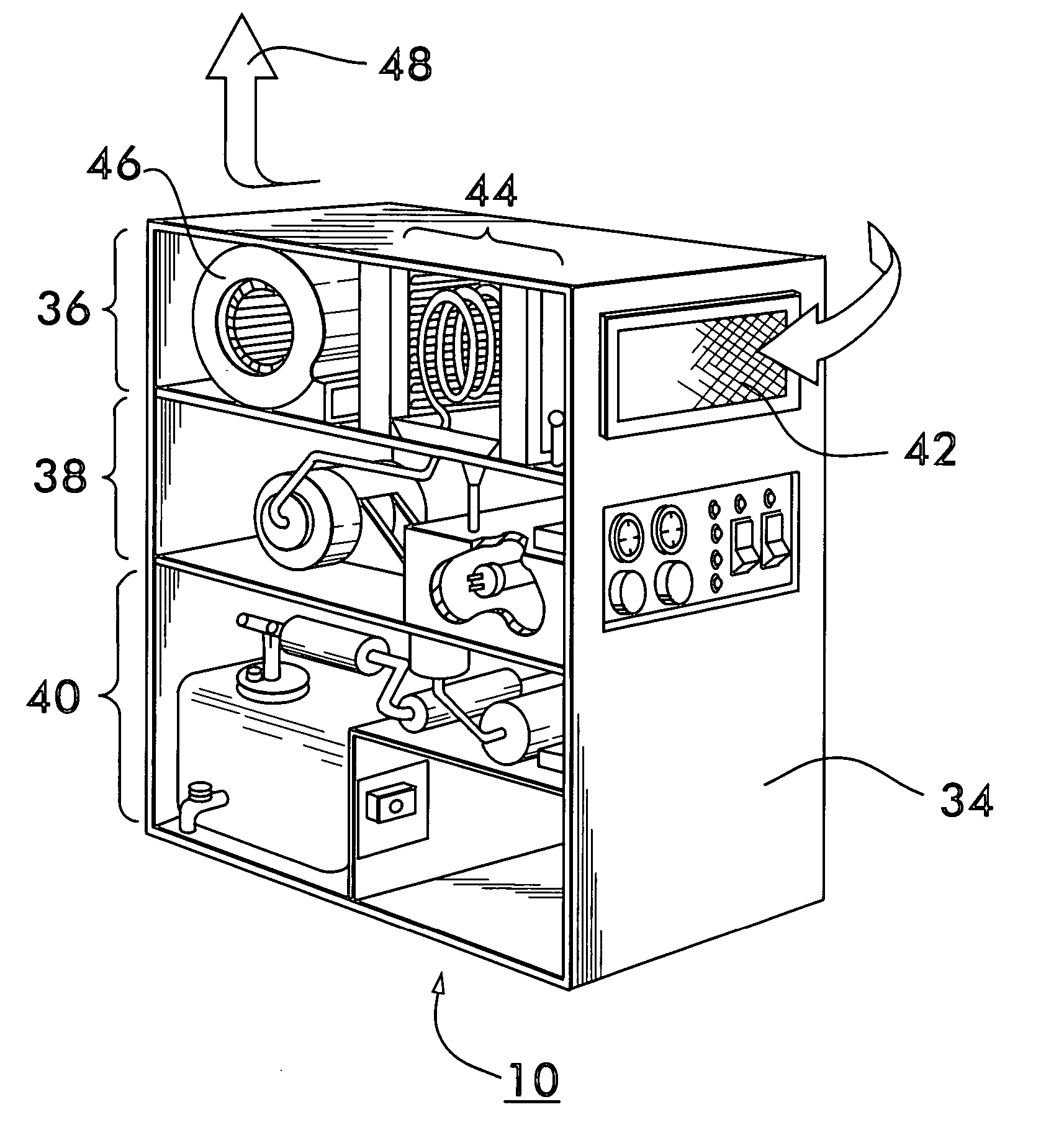
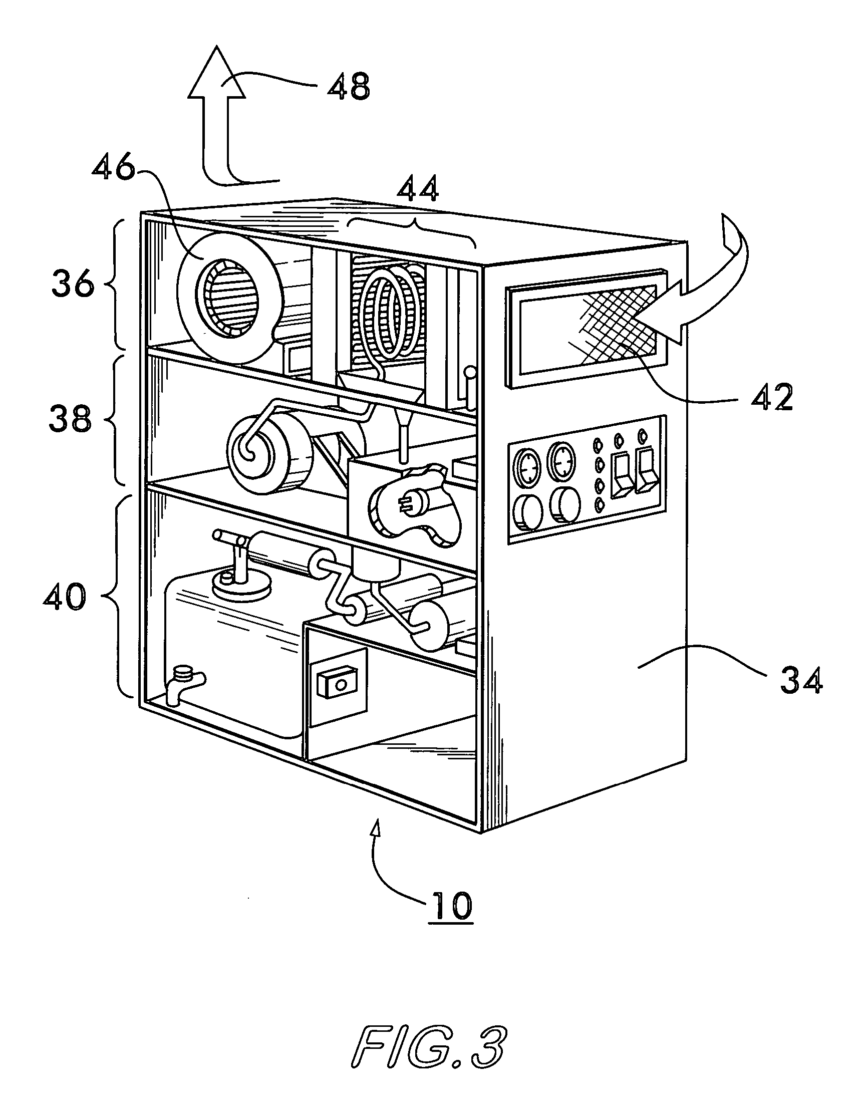
[0022] The Figures which accompany this application, and referenced herein, depict a representative embodiment of the energy recovery system adapted for use in conjunction with a portable air-water recovery facility. In the embodiments of this invention illustrated in these Figures, one or more components of the energy recovery system may appear in more than one Figure. Accordingly, components which are common to more than one Figure are assigned a common reference numeral for continuity of description and ease of understanding.

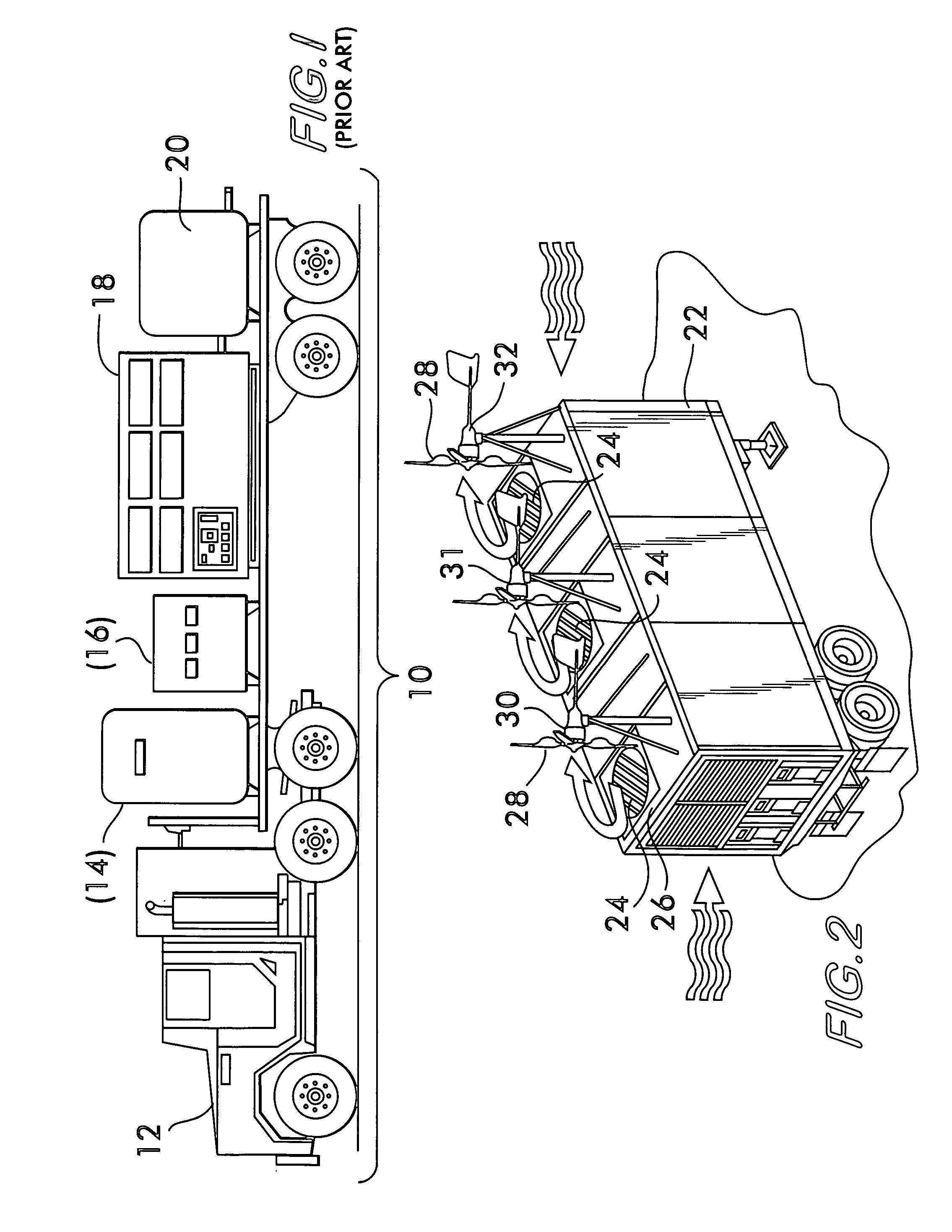
[0023]FIG. 1 depicts the prior art, specifically, a portable air-water recovery system (10) mounted on a flat bed truck (12). The basic components of this system (10) include a source of diesel fuel (14), a diesel generator (16) for production of electricity, a housing (18) containing the functional components of the air-water recovery system and a reservoir (20) for collection of the potable water produced by the air-water recovery system.

[0024] As depicte...


PUM

PropertyMeasurementUnit
Fractionaaaaaaaaaa
Pressureaaaaaaaaaa
Energyaaaaaaaaaa

Abstract

A mobile, self-propelled platform, which includes an enclosed trailer containing a portable air-water recovery system, is disclosed. This trailer includes a wind turbine mounted outside of the closed trailer environment, and adapted for recovery of energy from an exhaust air stream that is vented from within the enclosed trailer environment. The energy generated from such exhaust air stream is used to supplement traditional power sources associated with the operation of water generation process. The energy recovered from the exhaust air stream is projected to reduce the overall operating cost of the air-water recovery system by least 25%, based upon its current energy consumption needs. This system has application to other environments in which a force air stream is produce incident to operation of a primary process, as for example, where a high pressure, air dryer is used to remove moisture from a product, or to accelerate a curing operation.

Description

BACKGROUND OF THE INVENTION [0001] 1. Field of the Invention [0002] This invention relates to an energy recovery system for use in conjunction with a portable water recovery facility. More specifically, the invention is directed to the use of a dry air exhaust from an air-water recovery facility to propel at least one air turbine powered electrical generator associated with such facility. [0003] 2. Description of the Prior Art [0004] The use of air turbine powered electrical generators for harnessing wind energy and conversion thereof to electrical power is well-known. Typically, such air turbines are mounted on a post at a fixed location, and further provided with a vane to position the blades of the turbine into the wind or air stream, U.S. Pat. No. 6,800,965 (to Bartlett, issued Oct. 5, 2005) being representative of this class of device. [0005] Air turbine powered generators have also been adapted to mobile platforms, and the turbine blades propelled by an air stream created by t...

Claims


Application Information

Patent Timeline
IPC IPC(8): B63H1/06
CPCB01D5/0039F03D9/00Y02E10/72F05B2240/941Y02B10/30F05B2240/94Y02E10/728Y02E70/30Y02P70/10F03D9/11F03D9/25F03D9/32
Inventor ZWEBNER, MICHAEL J.
Owner ZWEBNER MICHAEL J
Why Eureka
Try Eureka