
Vehicle air system having an indicator device and method

a technology of vehicle air and indicator device, which is applied in the direction of drying machines, lighting and heating apparatus, and separation processes, etc., can solve the problems of affecting the operation of the brake system and other devices that rely on compressed air, inherently raising the temperature of the air, and producing contaminants such as oil

Active Publication Date: 2009-06-09
BENDIX COMML VEHICLE SYST LLC
View PDF18 Cites 29 Cited by
  • Summary
  • Abstract
  • Description
  • Claims
  • Application Information

AI Technical Summary

Benefits of technology

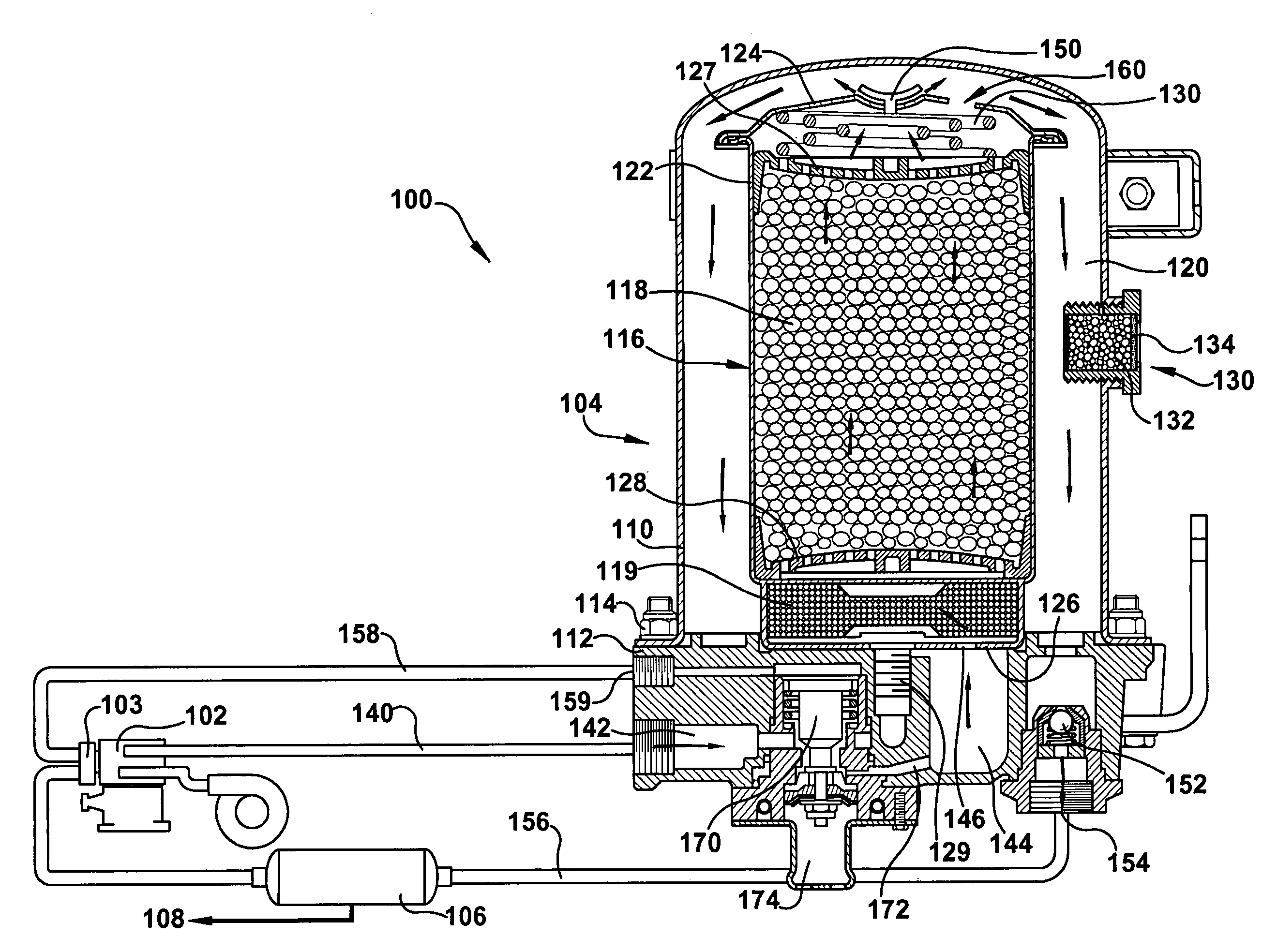
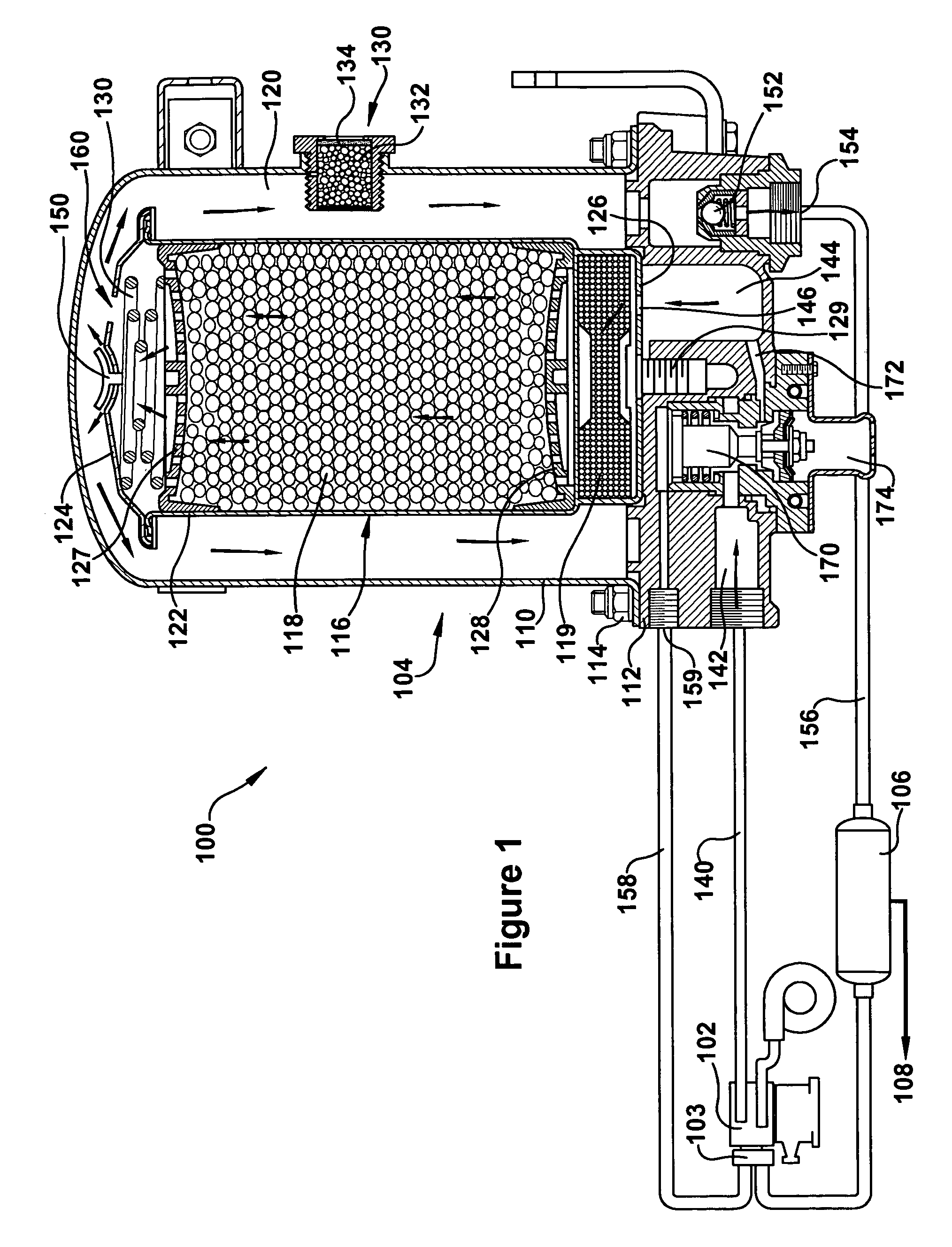
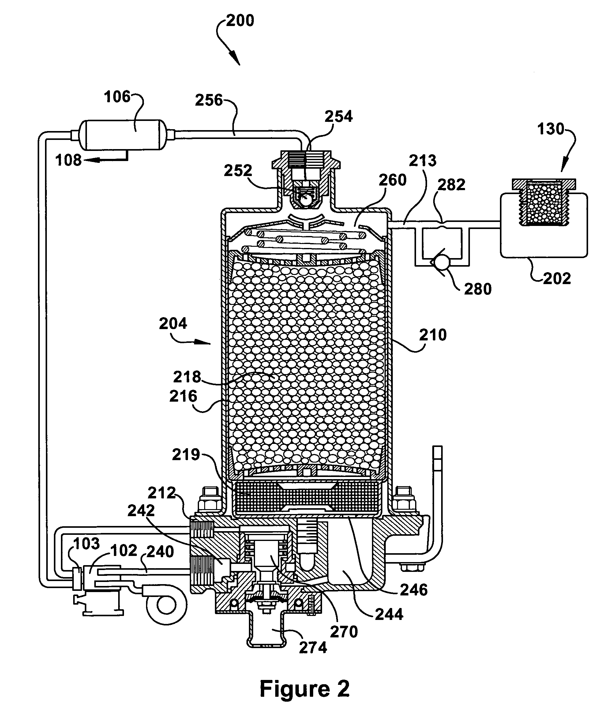
The present invention is about a vehicle air system that includes a device to monitor the humidity in the air. The system includes a compressor, an air dryer, and a purge reservoir with a special indicator material that changes color when the humidity reaches a certain level. This allows for easy monitoring of the air system and ensures that the air is always at the best quality. The invention also includes a dryer apparatus with a desiccant and an indicator device, and a method for monitoring the humidity in the air system.

Problems solved by technology

However, the operation of an air compressor inherently raises the temperature of the air and also produces contaminants such as oil.
The accumulation of water, oil and other contaminants present problems that can adversely affect the operation of the brake system and other devices that rely on the compressed air.
More specifically, moisture entrained in the air brake system may during cold weather operation cause the components of the air brake system to freeze, thus rendering the system inoperable.
If the dryer is a desiccant dryer, for example, a problem can exist in that once the desiccant is saturated with contamination the dryer ceases to perform the function of providing dry air.
It is difficult to know whether the desiccant needs to be replaced, and air dryers can be difficult to service because lines must be disconnected in order to remove the desiccant or desiccant canister.
However, there can often be temporary conditions such as excessive demand on the dryer that can affect the quality of the air through the system and therefore yield a false signal with regard to the desiccant.

Method used


Image

  • Vehicle air system having an indicator device and method
  • Vehicle air system having an indicator device and method
  • Vehicle air system having an indicator device and method

Examples


examples

[0047]The temperature of air at the dryer outlet in a commercial vehicle having a desiccant dryer was measured at various ambient temperatures. The dew point temperatures of the air at the dryer outlet, and the dew point suppression as defined above were calculated at the various humidity levels according to Table I.

[0048]

TABLE IDryerOutletAmbient5% RH10% RH15% RH20% RH25% RH30% RH40% RHTempTempDPTDPSDPTDPSDPTDPSDPTDPSDPTDPSDPTDPSDPTDPS° F.° F.° F.° F.° F.° F.° F.° F.° F.° F.° F.° F.° F.° F.° F.° F.10−30−4515−344−26−4−21−9−1713−1317−82220−20−3212−255−18−2−13−7−812−4161−2130−10−2919−177−9−1−4−61−114−1410−20400−2222−1010−224−48−812−1218−185010−1626−3135511−116−620−1026−166020−103041612819124−428−835−157030−3331119201026432−236−643−1380403371723271333739144−452−1290509412426331741947352−261−1110060164431294119491155561−170−1011070214938324921571364669179−912080275345355723651572878287−7

[0049]Various moisture indicator materials were tested for color change at various levels of moisture...


PUM

PropertyMeasurementUnit
temperatureaaaaaaaaaa

Abstract

Various compressed air systems for commercial vehicles are disclosed. In one embodiment, a compressed air system is provided that includes a compressor, an air dryer apparatus, a purge reservoir, and an indicator device. The indicator device comprises a moisture-indicating material that is in contact with the purge air within the purge reservoir.

Description

BACKGROUND[0001]This invention relates to vehicle air system, and more specifically to a commercial vehicle air system having a dryer apparatus.[0002]Commercial vehicles such as trucks, buses, and large commercial vehicles are typically equipped with a compressed air system in which the brakes of the vehicle are actuated by compressed air. An air compressor is often operated by the vehicle engine and generates pressurized air for the operation of air brakes and other devices that rely on pneumatic air. However, the operation of an air compressor inherently raises the temperature of the air and also produces contaminants such as oil. The accumulation of water, oil and other contaminants present problems that can adversely affect the operation of the brake system and other devices that rely on the compressed air. More specifically, moisture entrained in the air brake system may during cold weather operation cause the components of the air brake system to freeze, thus rendering the sys...

Claims


Application Information

Patent Timeline
Patent Type & Authority Patents(United States)
IPC IPC(8): B01D53/02
CPCB01D53/0415B01D53/261B60T17/004B01D2253/106B01D2253/112B01D2253/20B01D2257/80B01D2259/40081B01D2259/40086B01D2259/4566Y10S55/17Y10S55/34
Inventor FORNOF, WILLIAM P.
Owner BENDIX COMML VEHICLE SYST LLC
Learn More