

Compressed air processing apparatus for compressed air systems of motor vehicles
- Summary
- Abstract
- Description
- Claims
- Application Information
AI Technical Summary
Benefits of technology
Problems solved by technology
Method used
Image

Examples
Embodiment Construction
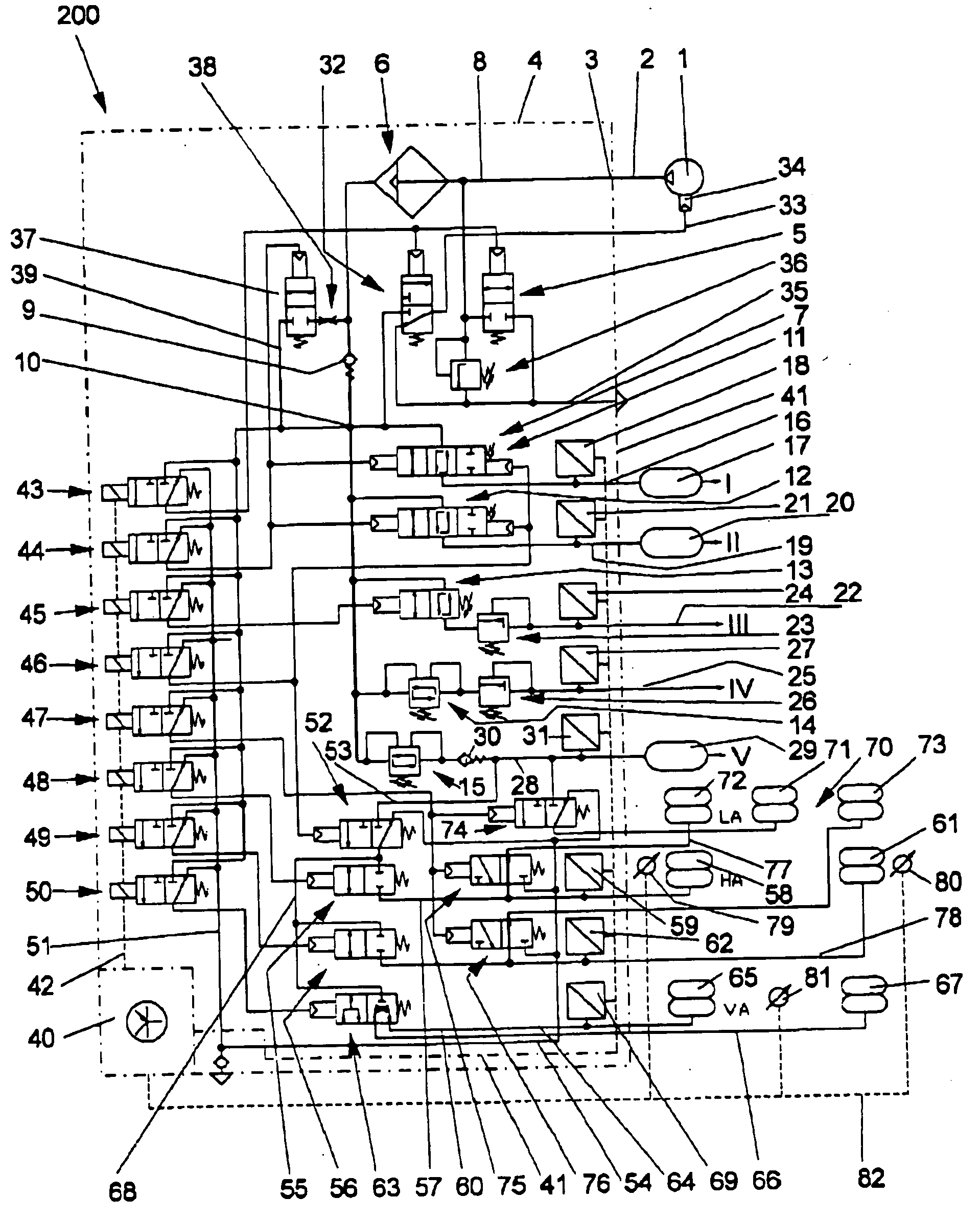
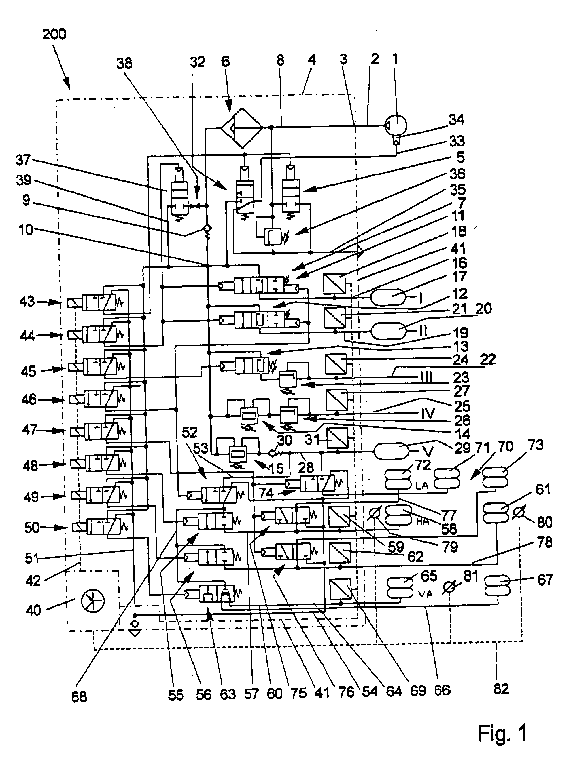
[0029] Referring now in greater detail to the drawings, FIG. 1 and all following figures illustrate the pneumatic elements, parts, components and conduits by a continuous line, while electric lines are illustrated by a broken line.
[0030] The compressed air processing apparatus 200 includes a compressor 1 from which a pneumatic conduit 2 leads to a connection 3 being located at a structural unit 4. The structural unit 4 may especially be designed as a common housing. A pressure controller 5, an air dryer 6 and a multi-circuit protection valve 7 are located in the structural unit 4, and they are schematically illustrated in FIG. 1. These elements are designed and interconnected in a way which is well-known in the art and such that they fulfill the known function of processing compressed air.
[0031] A conduit 8 leads from the connection 3 to the air dryer 6 and to a check valve 9 at which the central aerating system 10 begins. The central aerating system 10 is to be understood as a ch...
PUM
 Abstract
Description
Claims
Application Information