Display control system of a display panel and control method thereof

a display panel and control system technology, applied in static indicating devices, instruments, electroluminescent light sources, etc., can solve the problems of significantly distorting the displayed image, unbalanced brightness of the display panel, and less than the right side and the left side of the display panel

Active Publication Date: 2009-10-27
PRINCETON TECH CORP
View PDF3 Cites 172 Cited by
  • Summary
  • Abstract
  • Description
  • Claims
  • Application Information

AI Technical Summary

Problems solved by technology

If the distribution of driving currents of OLEDs of one scan line is not uniform, it results in a defect in which the brightness of the display panel is unbalanced or that the brightness of the display panel near the right side and the left side of the display panel is less than a standard level.
Especially in the fabrication of large-sized panels, the unbalanced brightness of the display panel may cause gray-scale value shifts between areas in the display panel, which considerably distorts the displayed image.

Method used


Image

  • Display control system of a display panel and control method thereof
  • Display control system of a display panel and control method thereof
  • Display control system of a display panel and control method thereof

Examples


Embodiment Construction

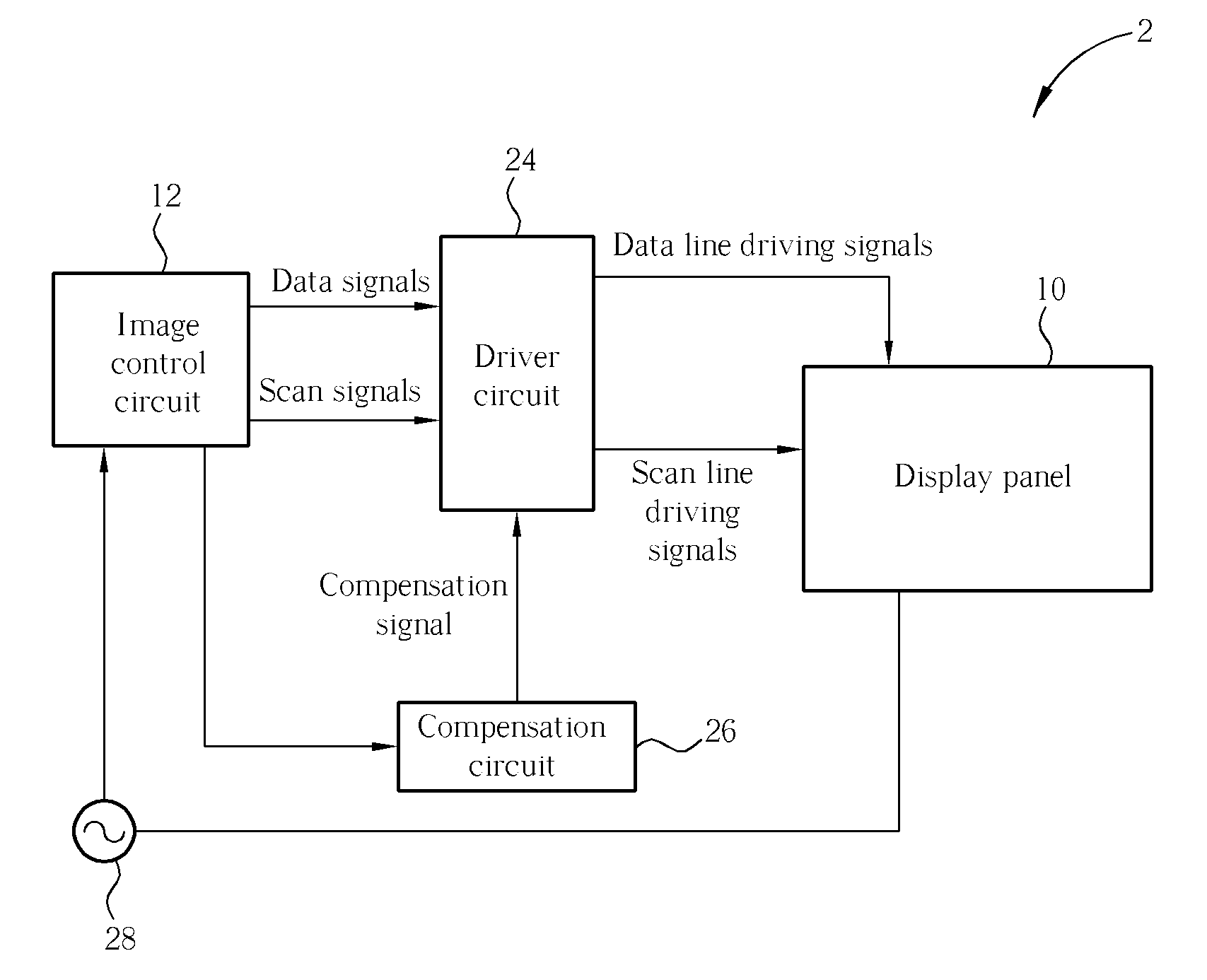
[0024]A display control system according to the present invention compensates data line driving signals to average the magnitude of currents. Please refer to FIG. 5, which is a block diagram of a display control system 2 according to the present invention. The display control system 2 comprises a display panel 10, an image control circuit 12, a driver circuit 24, a compensation circuit 26, and a current meter 28. The current meter 28 is used to measure the distribution and the magnitude of the currents flowing through the scan lines of the display panel 10. The image control circuit 12 sends a control signal to the compensation circuit 26 according to the distribution and the magnitude of the currents measured by the current meter 28. The compensation circuit 26 generates a compensation signal according to the distribution of current flowing through the scan line of the display panel 10. The driver circuit 24 receives data signals and scan signals from the image control circuit 12 a...


PUM


Abstract

When electric current is provided to a scan line of a display panel, electric current flowing from an initial end to a final end of the scan line is gradually reduced because of resistance consumption, resulting in lower brightness on both left and right sides of the display panel. Therefore, data line driving signals provided to the display panel are compensated for solving such a problem.

Description

BACKGROUND OF THE INVENTION[0001]1. Field of the Invention[0002]The present invention is related to a display control system and a related method, and more particularly, to a display control system of a display panel and a related method.[0003]2. Description of the Prior Art[0004]An organic light-emitting diode (OLED) is a current-driven electric lighting element having a brightness that depends on the magnitude of a related current. At present, the magnitude of the brightness (which is also called the gray-scale value) is controlled by the magnitude of the OLED driving current in an application OLED matrix display.[0005]Please refer to FIG. 1 and FIG. 2. FIG. 1 is block diagram of a display control system 1 according to the prior art, and FIG. 2 is a schematic diagram of a display panel 10 of the display control system 1. The display control system 1 comprises the display panel 10, an image control circuit 12, and a driver circuit 14. The image control circuit 12 generates data sig...

Claims


Application Information

Patent Timeline
Patent Type & Authority Patents(United States)
IPC IPC(8): G09G3/32H05B44/00
CPCG09G3/3208G09G3/2011G09G3/2014G09G2320/029G09G2320/0223G09G2320/0285G09G2310/0232
Inventor CHANG, HWA-HSIANG
Owner PRINCETON TECH CORP
Why Eureka
Try Eureka