Finger identification method and apparatus

a finger and finger technology, applied in the field of biometric personal identification apparatus, can solve the problems of insufficient use of light irradiated to the finger, inability to obtain the correct blood vessel pattern, and limited the supposed range of external light variation, so as to achieve optimum picture quality, reduce energy consumption, and improve identification precision

Active Publication Date: 2009-10-27
HITACHI ASTEMO LTD
View PDF8 Cites 24 Cited by
  • Summary
  • Abstract
  • Description
  • Claims
  • Application Information

AI Technical Summary

Benefits of technology

[0011]An object of the present invention is to provide an image pickup scheme capable of always providing an optimum quality of a blood vessel pattern without being affected by a difference, if any, in an external environment ranging from an ordinary indoor environment to an outdoor environment in which remarkably intense external light is present.
[0012]Another object of the present invention is to actively utilize external light as one of the light sources for picking up an image of a blood vessel pattern and thereby enhance the energy saving performance.
[0015]According to the present invention, the power control in the light sources for image pickup and the sensitivity control in the image pickup unit are adaptively combined according to the situation regardless of the external light around the identification apparatus. As a result, the finger portion in the picked up image is controlled to have an optimum picture quality. Therefore, the blood vessel pattern in the image becomes clear, and the identification precision can be improved. Furthermore, since external light is utilized as one of the light sources for image pickup, the energy consumption quantity required for the identification can be reduced.

Problems solved by technology

Therefore, the difference between brightness and darkness in the blood vessel portion does not appear, and a correct blood vessel pattern cannot be obtained.
However, the method is premised on the indoor use, and the supposed range of the external light variation is also limited.
Furthermore, in the case described above, light irradiated to the finger cannot be utilized suitably although it has a quantity enough to pick up an image of the blood vessel pattern.
As a result, energy is supplied to the light sources dedicated to image pickup unnecessarily.
However, the mere application of the AGC to the camera for picking up an image of a blood vessel does not make it possible to obtain a clear blood vessel pattern.
Therefore, suitable image pickup is impossible unless the sensitivity is controlled after it is ascertained well that light for picking up an image of the blood vessel pattern is sufficiently supplied.
Unless there is such cooperation, the power of the light sources and the sensitivity of the camera might interfere with each other in attempting a suitable picture quality and eventually convergence to a suitable picture quality might be not attained.
Therefore, the finger portion in the picked up image does not necessarily become optimum in picture quality.
For example, when a great difference is caused in brightness between the inside of the finger and the background by external light, or when only a portion of the finger directly exposed to light from the light sources for image pickup is locally bright, the gain is set to an excessively low value by strong influence of the brightness and consequently the finger portion for which an optimum picture quality should be originally obtained becomes too dark in its image.
Even if external light having intensity enough to obtain the blood vessel pattern is applied to the finger, it cannot be utilized sufficiently in situations where the light source power control and the sensitivity control in the AGC or the like operate asynchronously.
This is wasteful energy consumption.
Especially in the case of energy supply using a battery or the like, the sustaining time of the battery is shortened and there is a problem from the viewpoint of preservation of the global environment as well.

Method used


Image

  • Finger identification method and apparatus
  • Finger identification method and apparatus
  • Finger identification method and apparatus

Examples


Embodiment Construction

[0027]Hereafter, an embodiment of the present invention will be described in detail.

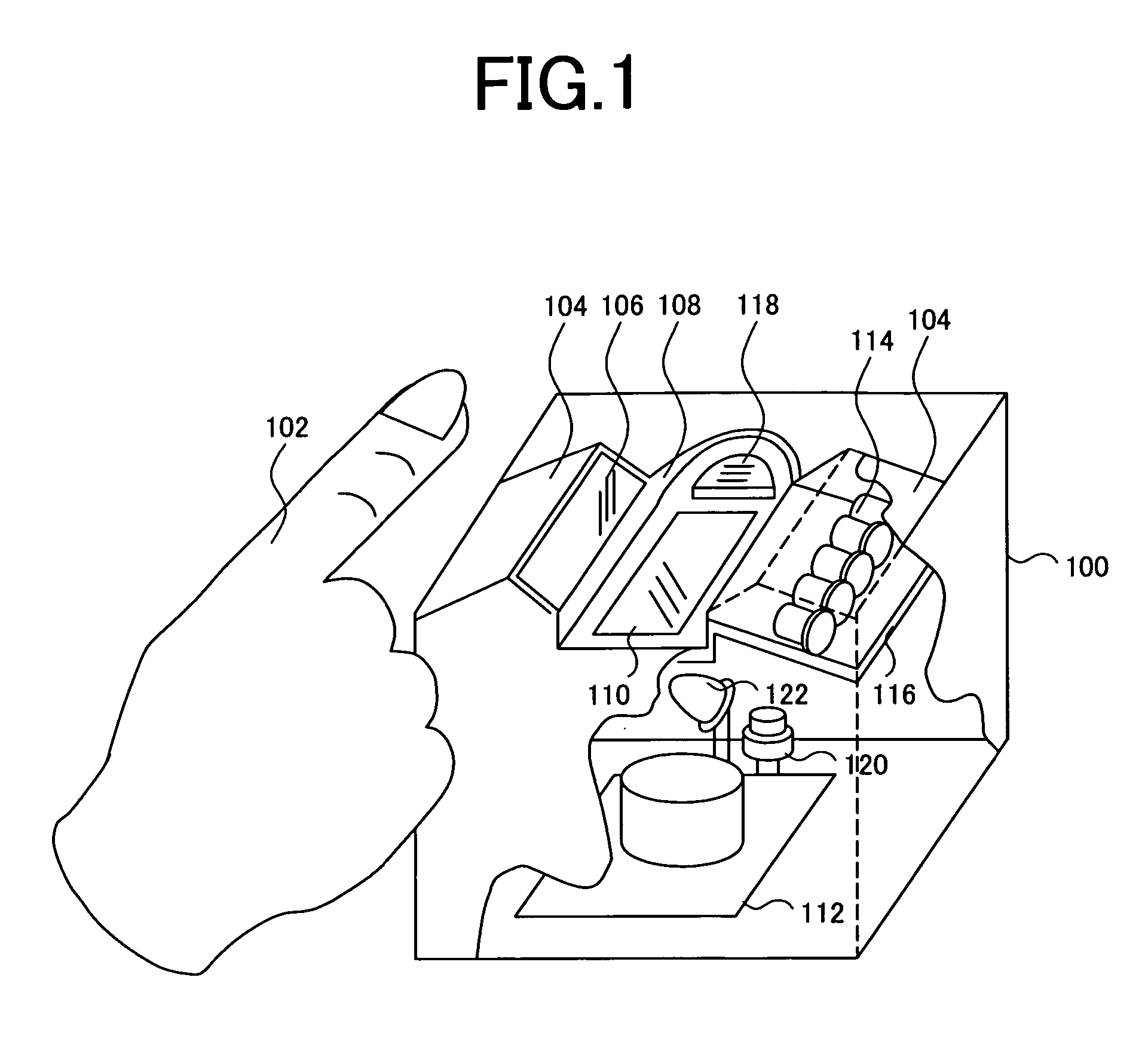
[0028]FIG. 1 is a schematic diagram of an identification apparatus 100, which implements the present invention. On a top surface of a main body, there is a guide groove 108, which exhibits a place to place a finger 102 therein in an intuitively understandable form. Light source units 104 are disposed on the left and right sides of the guide groove 108. This guide groove has a function of serving as a low light shielding wall that hides the lower half side of the finger. It is possible to physically shield external light that streams from a low position into the finger. A blood vessel pattern to be picked up as an image is present on the lower half side of the finger. When light irradiated from the left and right light sources is scattered in the finger and output from the lower side of the finger, a pattern based on the contrast between brightness and darkness is formed by a difference in light absor...


PUM


Abstract

An image pickup scheme capable of always providing an optimum quality of a blood vessel pattern, in image pickup of a blood vessel pattern of a finger using transmitted light, without being affected by a difference, if any, in an external environment. A personal identification apparatus includes light sources for irradiating light to be transmitted by a finger, an image pickup unit for picking up an image using light transmitted by the finger, finger detection unit for detecting that the finger exists in a predetermined position, finger region extraction unit for extracting a region occupied by the finger from an image picked up by the image pickup unit, and gain changing unit for changing an amplification factor of image pickup elements in the image pickup unit on the basis of a picture quality of a specific region within the extracted region.

Description

CROSS-REFERENCE TO RELATED APPLICATION[0001]The present invention is related to U.S. application Ser. No. 10 / 617,828 filed Jul. 14, 2003, the entire content of which is incorporated herein by reference.INCORPORATION BY REFERENCE[0002]The present application claims priorities from Japanese applications JP 2005-245241 filed on Aug. 26, 2005, JP 2004-321454 filed on Nov. 5, 2004, the contents of which are hereby incorporated by reference into this application.BACKGROUND OF THE INVENTION[0003]The present invention relates to a personal identification apparatus using a living body. In particular, the present invention relates to a biometric personal identification apparatus based on a blood vessel (vein) pattern of a finger.[0004]As a security scheme that does not need carrying a key or the like, that is high in convenience, and that is little fear of illegal use such as loss and theft, attention is paid to biometrics using a part of an individual's body, such as a finger print, iris, a ...

Claims


Application Information

Patent Timeline
Patent Type & Authority Patents(United States)
IPC IPC(8): G06K9/00A61B5/117G06T1/00
CPCA61B5/1172A61B5/489B60R25/252B60R25/255G06K9/00033B60R25/25A61B2562/0233A61B2562/046G06K2009/00932G06V40/1312G06V40/14G06T1/00G06F18/00
Inventor NAGASAKA, AKIOMIURA, NAOTOMIYATAKE, TAKAFUMI
Owner HITACHI ASTEMO LTD
Why Eureka
Try Eureka