Fuel vapor treatment system

a technology of fuel vapor treatment and treatment system, which is applied in the direction of combustion-air/fuel-air treatment, electric control, instruments, etc., can solve the problems of air-fuel ratio disturbance, and achieve the effect of restricting a disturbance of air-fuel ratio and ensuring enduran

Inactive Publication Date: 2009-11-03
DENSO CORP
View PDF17 Cites 12 Cited by
  • Summary
  • Abstract
  • Description
  • Claims
  • Application Information

AI Technical Summary

Benefits of technology

[0006]The present invention is made in view of the above matters, and it is an object of the present invention to provide a fuel vapor treatment system which is able to restrict a disturbance of air-fuel ratio of an internal combustion engine and to ensure its endurance.
[0009]According to the present invention, by considering a change in a reference condition quantity which is detected as the fuel vapor condition quantity, the detection interval is set shorter to restrict the disturbance of the air-fuel ratio. Furthermore, in a case that the fuel vapor is hardly desorbed from the adsorbent, since a change in fuel vapor condition quantity is small, the detection interval can be set longer in a range where the disturbance of the air-fuel ratio is restricted. The detection interval is made longer according to the situation. Hence an operation frequency of the gas generating means is reduced and its endurance is improved.

Problems solved by technology

If the detection interval is excessively long, the air-fuel ratio may be disturbed.

Method used


Image

  • Fuel vapor treatment system
  • Fuel vapor treatment system
  • Fuel vapor treatment system

Examples


first embodiment

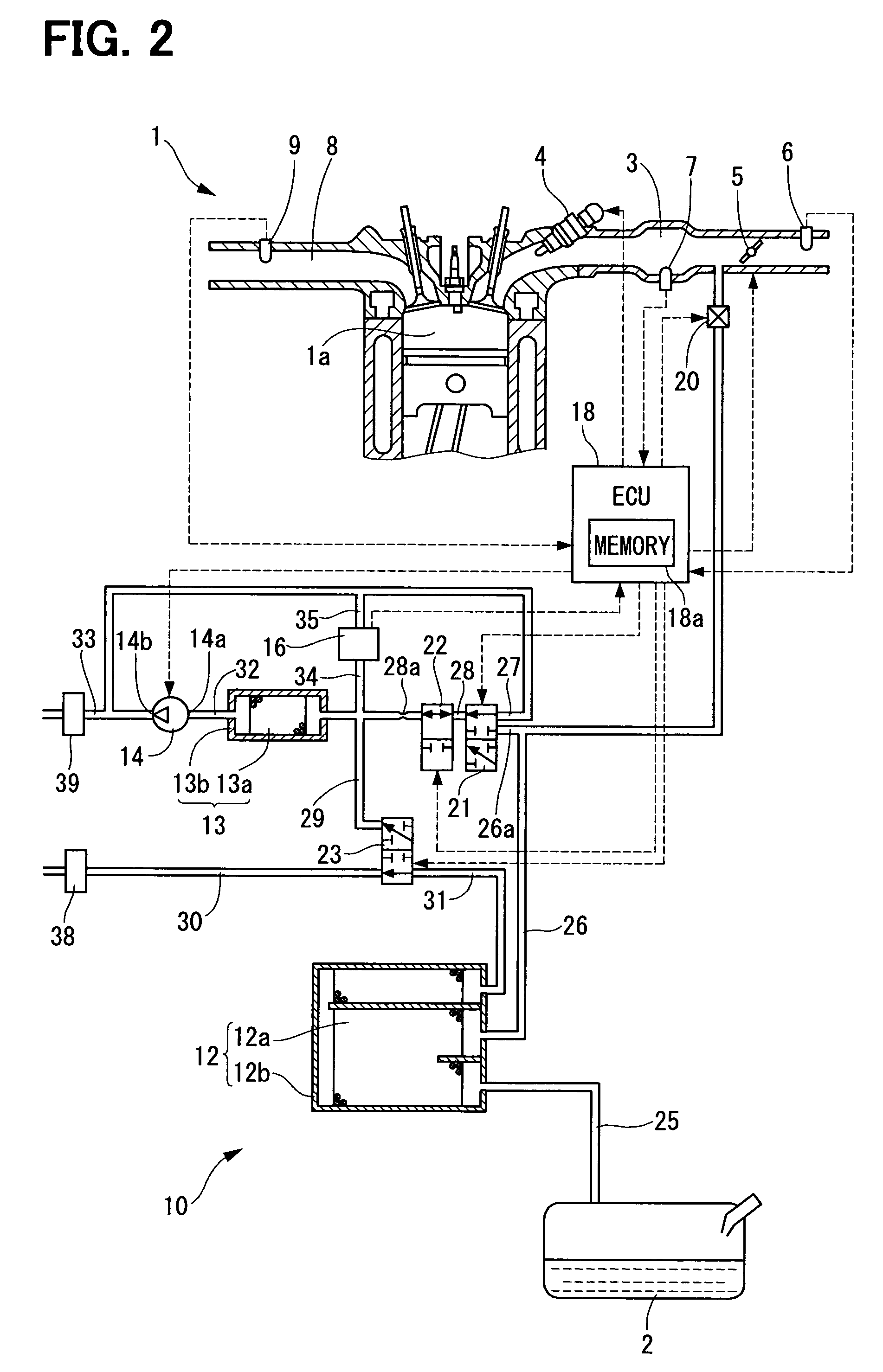
[0027]FIG. 2 shows a first embodiment of a fuel vapor treatment system 10 which is applied to an internal combustion engine 1.

(Internal Combustion Engine)

[0028]The internal combustion engine 1 is a gasoline engine which generates power using gasoline accommodated in an interior of a fuel tank 2. An intake pipe 3 of the engine 1 is provided with a fuel injector 4 which controls a fuel injection quantity, a throttle valve 5 which controls an intake air flow rate, an intake air flow rate sensor 6 which detects an intake air flow rate, and a intake air pressure sensor 7 which detects intake air pressure. An exhaust pipe 8 of the engine 1 is provided with an air-fuel ratio sensor 9 which detects an exhaust gas air-fuel ratio.

(Fuel Vapor Treatment System)

[0029]The fuel vapor treatment system 10 is the apparatus for treating the fuel vapor generated in the fuel tank 2, and burning the fuel vapor with the injected fuel by the fuel injector 4. The fuel vapor treatment system 10 is specifical...

second embodiment

[0067]FIG. 7 is a flowchart showing a second embodiment which is a modification of the first embodiment.

[0068]S102, S103, S105, and S106 in the first embodiment are respectively replaced by S201, S202, S203, and S204.

[0069]In S201, the pressure ΔPAir, Pt, ΔPGas are detected and the fuel vapor concentration D is computed. This concentration D is stored in the memory 18a as a first reference concentration Db. At this moment, the first reference concentration Db previously stored in the memory 18a is remained in the memory 18a as a second reference concentration Db. The second reference concentration Db stored in the memory is the latest value of the detected value of the fuel vapor concentration D in the previous concentration detection process and the adapted value of the fuel vapor concentration D is the latest purge control process. At the first concentration detection process, since the second reference concentration Db does no exist in the memory 18a, the first reference concentr...

third embodiment

[0076]As shown in FIG. 9, the third embodiment is a modification of the first embodiment.

[0077]In the third embodiment, S301 and S302 are respectively added after S103 and S106 of the first embodiment, so that the detection interval ΔT is corrected.

[0078]In S301, a first correction process is executed so that the detection interval ΔT is corrected based on an inner pressure P of the fuel tank 2. This is because that when the inner pressure P in the fuel tank increases, the fuel vapor quantity in the fuel tank is increased. The adsorbed quantity “A” in the first canister 12 increases and the fuel vapor concentration D in the purge passage 26 tends to be easily changed.

[0079]In the first correction process, a correction coefficient Cp is computed according to the current inner pressure P. As shown in FIG. 10, as the inner pressure P increases, the correction coefficient Cp becomes smaller. The stored interval ΔT is multiplied by the correction coefficient Cp to correctly update the de...


PUM


Abstract

A fuel vapor treatment system which has adsorbent, a purge passage for introducing a mixture gas of air and the fuel vapor desorbed from the adsorbent into the internal combustion engine, a detection passage which communicates to the purge passage, and a pump which generates gas flow so that the mixture gas flows into the detection passage from the purge passage. A pressure sensor detects fuel vapor concentration. An ECU and a purge control valve controls a purge of the mixture gas from the purge passage to the internal combustion engine based on a reference concentration of the fuel vapor. The ECU establishes the detection interval of the fuel vapor concentration in consideration of change in reference concentration.

Description

CROSS-REFERENCE TO RELATED APPLICATION[0001]This application is based on Japanese Patent Application No. 2007-166846 filed on Jun. 25, 2007, the disclosure of which is incorporated herein by reference.FIELD OF THE INVENTION[0002]The present invention relates to a fuel vapor treatment system treating a fuel vapor which is combusted with injected fuel of an internal combustion engine.BACKGROUND OF THE INVENTION[0003]In the fuel vapor treatment system, fuel vapor generated in a fuel tank is temporarily adsorbed by adsorbent in a canister. Desorbed fuel vapor is mixed with air and is purged into the internal combustion engine, so that the fuel vapor is combusted with injected fuel in a combustion chamber of the internal combustion engine. In a system shown in JP-2006-312925A (US2006 / 0225713A1), fuel vapor concentration of the mixture gas is detected to correctly control the quantity of the purge gas.[0004]Specifically, a purge passage is connected to a detection passage. The mixture gas...

Claims


Application Information

Patent Timeline
Patent Type & Authority Patents(United States)
IPC IPC(8): F02M33/02F02D45/00F02M25/08
CPCF02M25/089F02M25/0827
Inventor TAKAKURA, SHINSUKEKANO, MASAO
Owner DENSO CORP
Why Eureka
Try Eureka