Extensible aerial boom having two independently operated fluid nozzles

a technology of fluid discharge nozzle and aerial boom, which is applied in the direction of applications, roads, roads, etc., can solve the problems of affecting the operation of the boom system. , to achieve the effect of avoiding unnecessary shock to the boom system

Active Publication Date: 2009-11-03
OSHKOSH CORPORATION
View PDF9 Cites 18 Cited by
  • Summary
  • Abstract
  • Description
  • Claims
  • Application Information

AI Technical Summary

Benefits of technology

[0009]The present invention provides an improved upper extensible boom for a fire fighting vehicle, the extensible boom having a stationary portion and an extensible portion with a first low volume fluid discharge nozzle and a piercing nozzle mounted on the outer end of the extensible portion and a second high volume fluid discharge nozzle associated with the outer end of the stationary portion. Each of the fluid discharge nozzles is independently controlled so that two different fires, occurring in two adjacent or nearby areas, can be separately addressed and fought simultaneously.
[0010]The piercing nozzle on the outer end of the upper extensible boom is individually controllable with respect to the low volume fluid discharge nozzle for movement only in the vertical plane. It also has a power source, preferably a hydraulic system, for selectively forcing the piercing nozzle through a wall structure such as the outer skin of an aircraft so that, when the tip of the nozzle touches the wall or skin of an aircraft, at any angle to the longitudinal axis of the extensible boom, the hydraulic system can force the piercing nozzle through the wall without damage to the piercing nozzle.
[0011]Inasmuch as the upper extensible boom is pivotally mounted at its inner end to the outer end of the lower boom and the lower boom is pivotally mounted at its inner end to the vehicle, a first hydraulic cylinder is placed between the vehicle and the outer end of the lower boom to raise and lower the lower boom in the vertical plane. A second hydraulic cylinder is coupled between the vehicle and the inner end of the upper boom to raise and lower the upper boom in the vertical plane with respect to any vertical position of the lower boom. The second hydraulic cylinder is substituted for the sliding links in the prior art system and eliminates corrosion problems with the links.

Problems solved by technology

Inasmuch as fires may erupt or break out at any moment in different adjacent or nearby spots or areas, it is impossible for the systems of the prior art to confront or fight two fires in different nearby areas simultaneously.
If these requirements were not so and the longitudinal axis of the piercing nozzle was out of alignment with the longitudinal axis of the boom, as the boom moves forward to cause the piercing nozzle to pierce the wall, a stress moment arm is placed upon the piercing nozzle and may snap if off of its mountings or otherwise damage it.
As the boom moves downwardly in an arc as shown in FIG. 12 in the '756 patent to force the piercing nozzle through the wall (or skin of an aircraft), the piercing nozzle can be damaged if its longitudinal axis is NOT perpendicular to the boom longitudinal axis.
Such sudden stops place a great deal of stress on the fluid discharge nozzles and other components by the sudden change of speed of the extensible boom.
There is no possibility of individually controlling two nozzles to allow two adjacent or nearby fires to be attacked or fought simultaneously.
This system completes its task well but corrosion internal of the slidable sections causes added stress to be placed on the links and requires difficult maintenance.

Method used


Image

  • Extensible aerial boom having two independently operated fluid nozzles
  • Extensible aerial boom having two independently operated fluid nozzles
  • Extensible aerial boom having two independently operated fluid nozzles

Examples


Embodiment Construction

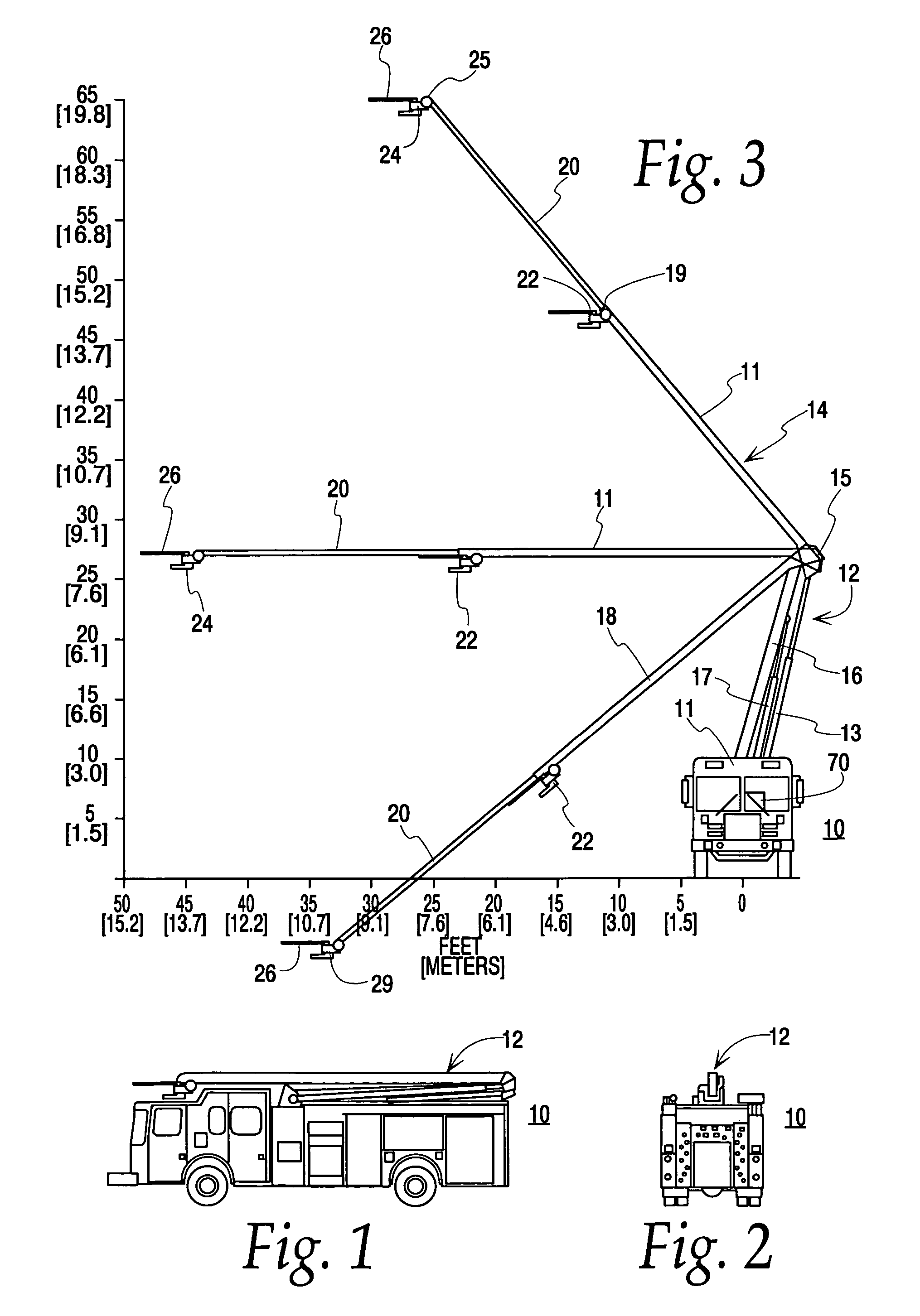
[0028]FIG. 1 is a side view of a fire fighting vehicle 10 illustrating the novel boom system 12 in its cradled or nested position for travel.

[0029]FIG. 2 is a rear-end view of the fire fighting vehicle 10 of FIG. 1 illustrating the novel boom system 12 in its cradled or nested position for travel.

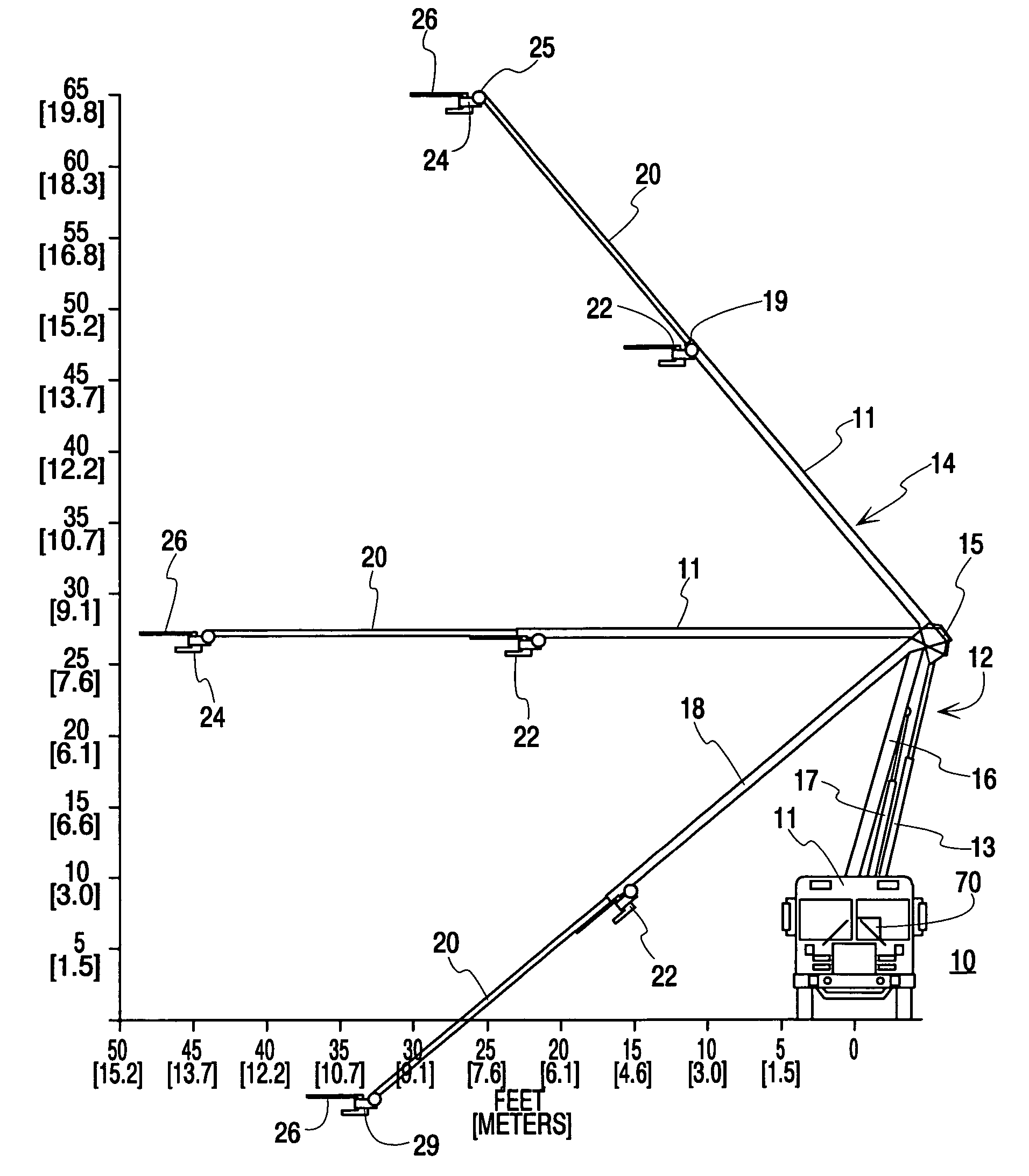
[0030]FIG. 3 is a front-end view of the fire fighting vehicle 10 of FIG. 1 and FIG. 2 illustrating the novel boom system 12 with an upper extensible boom 14 and a lower, fixed length, boom 16 and showing both the upper extensible boom 14 in its uppermost extensible position, a medium height extensible position, and its lowermost extensible position and the lower fixed length boom 16 is its uppermost position. It will be noted that the lower, fixed length, boom 16 is raised and lowered in the vertical plane by a hydraulic cylinder 17. It will also be noted that the inner end 15 of the upper extensible boom 14 is directly connected to one end of hydraulic cylinder 13 and the opposite end of t...


PUM


Abstract

A novel aerial boom system for use atop a vehicle and having linear movement sensors associated with hydraulic cylinders for moving lower and upper booms such that a microprocessor associated with the system can determine the instantaneous position of each boom and coordinate movement of the booms with respect to each other and with the vehicle to prevent undesired contact and to gradually decelerate boom movement as the boom approaches its limits to avoid shock from sudden stop of boom movement. When the novel system is used with a fire fighting vehicle, two variably spaced, independently controllable, fluid discharge nozzles can be used to fight one or two separate and distinct fires simultaneously. A piercing nozzle can be associated with the outer end of the upper boom that is independently controllable in both the vertical plane and in the horizontal direction to enable piercing of a wall independent of boom movement to assist penetration.

Description

FIELD OF THE INVENTION[0001]The present invention relates in general to extensible aerial booms for fire fighting equipment and, in particular, to an extensible aerial boom that has two independently articulated and independently operated fluid flow nozzles each with a different fluid flow thereby enabling two localized, but separate, fires to be fought simultaneously.BACKGROUND OF THE INVENTION[0002]In the prior art, an elongated, extensible, boom has a fluid dispersing nozzle on the outer end thereof along with a piercing nozzle. Either nozzle can be used but they are used separately and almost never used together. Their use is directed to confront a single fire. Inasmuch as fires may erupt or break out at any moment in different adjacent or nearby spots or areas, it is impossible for the systems of the prior art to confront or fight two fires in different nearby areas simultaneously.[0003]In U.S. Pat. No. 5,839,664, a piercing nozzle moves in a vertical plane only with respect to...

Claims


Application Information

Patent Timeline
Patent Type & Authority Patents(United States)
IPC IPC(8): A01G25/09A62C27/00
CPCA62C27/00A62C31/02A62C31/28A62C31/24A62C31/22
Inventor RELYEA, ROBERT G.NORTH, GRADY C.
Owner OSHKOSH CORPORATION
Why Eureka
Try Eureka