Method and apparatus for electrochemical reduction of a solid feedstock

a solid feedstock and electrochemical reduction technology, applied in the field of electrochemical reduction methods and apparatuses, and to electrochemical products, can solve problems such as complex mechanical structures reduce or avoid problems such as corrosion or wear, and reduce heat loss from fused salts. , the effect of avoiding corrosion of the block or contamination

Active Publication Date: 2018-09-04
METALYSIS
View PDF15 Cites 1 Cited by
  • Summary
  • Abstract
  • Description
  • Claims
  • Application Information

AI Technical Summary

Benefits of technology

[0018]The cathode, contacting the feedstock, is preferably of a non-magnetic material, such as stainless steel or titanium, in order to reduce the risk of magnetic fields, generated by current flows during electro-reduction, affecting the movement of the cathode and the transport apparatus. In addition, the material of the cathode should preferably be inert in the presence of the feedstock and / or the product, while immersed in the fused salt.
[0024]At least one cathode support engaged with the cathode may be electrically conductive and in electrical contact with the cathode, to conduct electricity to the cathode. The cathode support may be electrically insulated from the fused salt, to reduce current leakage into the fused salt. The cathode support may, for example, comprise a conductive metal core shielded by a ceramic sheath
[0026]The cathode and the cathode transport apparatus advantageously comprise no moving parts which are exposed to the fused salt. The cathode may be removably engageable with the cathode transport apparatus, for example being removably engageable one or more cathode supports of the cathode transport apparatus, but when the cathode is engaged with the cathode transport apparatus it is preferred that no components of the cathode, or of the portion of the cathode transport apparatus which is exposed to or immersed in the fused salt, should move relative to one another. This may advantageously reduce or avoid problems of corrosion or wear in the cathode and the portions of the cathode transport apparatus immersed in the fused salt.
[0027]To carry out the electro-reduction process it is necessary to maintain the temperature of the fused salt at a predetermined temperature, typically of between 850 C and 1000 C, or preferably between 900 C and 970 C. In order to reduce heat losses from the fused salt it may be desirable to thermally insulate the container of fused salt. This may include providing thermal insulation within any openings between the wall of the container and the anode assembly. As described above, each cathode support may pass through such an opening. To provide thermal insulation, one or more of the cathode supports may comprise a thermally-insulating block for at least partially filling a portion of the corresponding opening in the region of the cathode support. The thermally-insulating block or each thermally-insulating block may advantageously be spaced from the fused salt during electro-reduction to avoid corrosion of the block or contamination of the salt. A flexible insulating material may be desirable, in order to accommodate any variations in the width of the opening through which the cathode support extends.
[0028]For additional thermal insulation, and to reduce any problems of corrosion of the side walls of the container, it may be desirable to operate the electro-reduction apparatus such that a solid frozen layer of the fused salt is maintained on a side wall of the container. The cathode support or each cathode support may then advantageously be shaped so as to be spaced from any solidified layer of the fused salt on the side wall.
[0038]In such an existing production facility, the containers for fused salt and the anode assemblies may be of significant size. Such a container typically has a length greater than its width and, after conversion for electro-reduction of solid feedstocks, the direction of motion of the cathode may advantageously be parallel to the length of the container, in order to provide a suitable duration for the electro-reduction process. If the cathode is to pass below the anode(s), as in the preferred embodiments described above, the anode(s) must then be suspended, preferably above a central portion of the container. Support can conveniently be provided by means of a load-bearing beam extending along the length of the container, above the central axis of the container, supported by an A-frame at each end of the container. The anodes in conventional Hall-Hèroult cells are typically supported in this way.

Problems solved by technology

These proposed processes suffer a number of practical problems, such as the requirement for complex mechanical structures being immersed in the high-temperature, chemically-aggressive and corrosive environment of the fused-salt melt, and have not been successfully implemented.

Method used


Image

  • Method and apparatus for electrochemical reduction of a solid feedstock
  • Method and apparatus for electrochemical reduction of a solid feedstock
  • Method and apparatus for electrochemical reduction of a solid feedstock

Examples


first embodiment

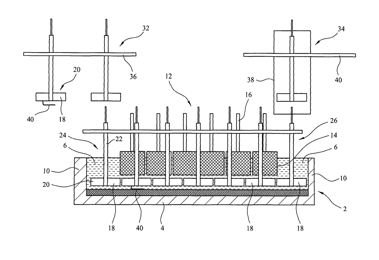
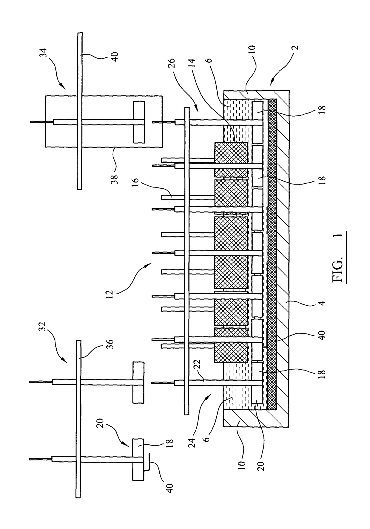
[0050]FIG. 1 is a schematic side view of an electro-reduction apparatus according to the invention, with a side wall of the fused-salt container removed to show the structure inside the container;

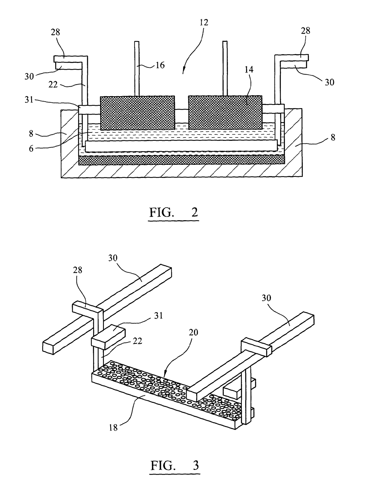
[0051]FIG. 2 is a transverse section through the apparatus of FIG. 1;

[0052]FIG. 3 is a three-quarter view of a loaded cathode and two cathode supports of the embodiment of FIGS. 1 and 2;

second embodiment

[0053]FIG. 4 is a transverse section of an apparatus according to the invention;

[0054]FIG. 5 is a schematic plan view of the electro-reduction apparatus of the first embodiment;

[0055]FIG. 6 is a three-quarter view of a cathode, loaded with feedstock;

third embodiment

[0056]FIG. 7 is a schematic transverse section of an electro-reduction apparatus according to the invention, illustrating side-loading of a cathode;

[0057]FIG. 8 is a transverse section of a conventional aluminium smelter cell;

[0058]FIG. 9 is a plan view of the anode arrangement in a conventional aluminium smelter cell;

[0059]FIG. 10 is a plan view of the aluminium smelter cell of FIG. 9, with the end anodes removed;

[0060]FIG. 11 is a plan view of an aluminium smelter cell showing a frame for supporting the anodes;

[0061]FIG. 12 is a plan view of an aluminium smelter pot-room, with cells arranged end-to-end;

[0062]FIG. 13 is a plan view of an aluminium smelter pot-room with cells arranged side-by-side; and

[0063]FIG. 14 is a plan view of the aluminium smelter pot-room of FIG. 13 modified for continuous solid-phase feedstock electro-reduction according to an embodiment of the invention.

[0064]FIGS. 1 and 2 show longitudinal and transverse sections of an electro-reduction apparatus accordin...


PUM

PropertyMeasurementUnit
electrically-conductiveaaaaaaaaaa
voltageaaaaaaaaaa
currentaaaaaaaaaa

Abstract

The method, apparatus and product relate to the electrochemical reduction of a solid feedstock (20) to produce a product. A container (2) is filled with a fused salt (6), and one or more anodes (14) contact the fused salt. A cathode (18) is loaded with feedstock and engages with a transport apparatus (22, 36, 40) which locates and moves the cathode past the anodes(s), while the cathode and the feedstock contact the fused salt. As the cathode moves past the anodes(s), a voltage applied between the cathode and the anode(s) electrochemically reduces the solid feedstock to form the product.

Description

CROSS-REFERENCE TO RELATED APPLICATION[0001]This application is the National Stage of International Application Number PCT / GB2012 / 050219, filed Feb. 2, 2012, which is hereby incorporated by reference herein in its entirety, including any figures, tables, nucleic acid sequences, amino acid sequences, or drawings.[0002]The invention relates to a method and an apparatus for electrolysis, and to an electrolysis product, and more particularly to a method and an apparatus for the continuous electrolysis of a solid feedstock to produce a solid product, and to the solid product.[0003]Electro-reduction or electro-decomposition is a method for processing a solid feedstock comprising a metal or a semi-metal and another substance, to remove some or all of the substance and produce a solid product. (In this document, for brevity, the term metal will be used to encompass metals and semi-metals in the context of the feedstock and the product.) The feedstock preferably comprises a compound between ...

Claims


Application Information

Patent Timeline
Patent Type & Authority Patents(United States)
IPC IPC(8): C25C7/00
CPCC25C7/005C25C7/007
Inventor WRIGHT, ALLEN RICHARD
Owner METALYSIS
Why Eureka
Try Eureka