Supercharge Your Innovation With Domain-Expert AI Agents!

Inkjet head

a head and inkjet technology, applied in the field of inkjet head, can solve the problems of large change in ink ejection speed, adversely affecting and degrading the quality of an image to be formed on the printing paper by the inkjet head, so as to achieve the effect of the same speed, the same volume and the same speed

Active Publication Date: 2009-11-03
BROTHER KOGYO KK +1
View PDF6 Cites 4 Cited by
  • Summary
  • Abstract
  • Description
  • Claims
  • Application Information

AI Technical Summary

Benefits of technology

The present invention provides an inkjet head that can print with good image quality by avoiding a sharp change in ink ejection speed near any maximal value and minimizing the difference in speed and volume between the first and second ink droplets. The invention achieves this by satisfying a condition that the ratio between the volume of a partial passage in the individual ink passage and the volume of the pressure chamber is not less than 0.12 and not more than 0.40. This condition ensures that the ink ejection speed does not sharply change near any maximal value and that the first and second ink droplets have similar speeds and volumes. The invention also includes an actuator that can change the volume of the pressure chamber to achieve the desired ink ejection speed.

Problems solved by technology

In such an inkjet head, because the ink ejection speed sharply changes near each maximal value, a little change in the width of the ejection pulse may bring about a large change in the ink ejection speed.
This adversely affects the quality of an image to be formed.
Because the high-speed small ink droplet impacts a printing paper at an earlier timing than the normal ink droplets, this degrades the quality of an image to be formed on the printing paper by the inkjet head.

Method used


Image

  • Inkjet head
  • Inkjet head
  • Inkjet head

Examples


Embodiment Construction

General Construction of Printer

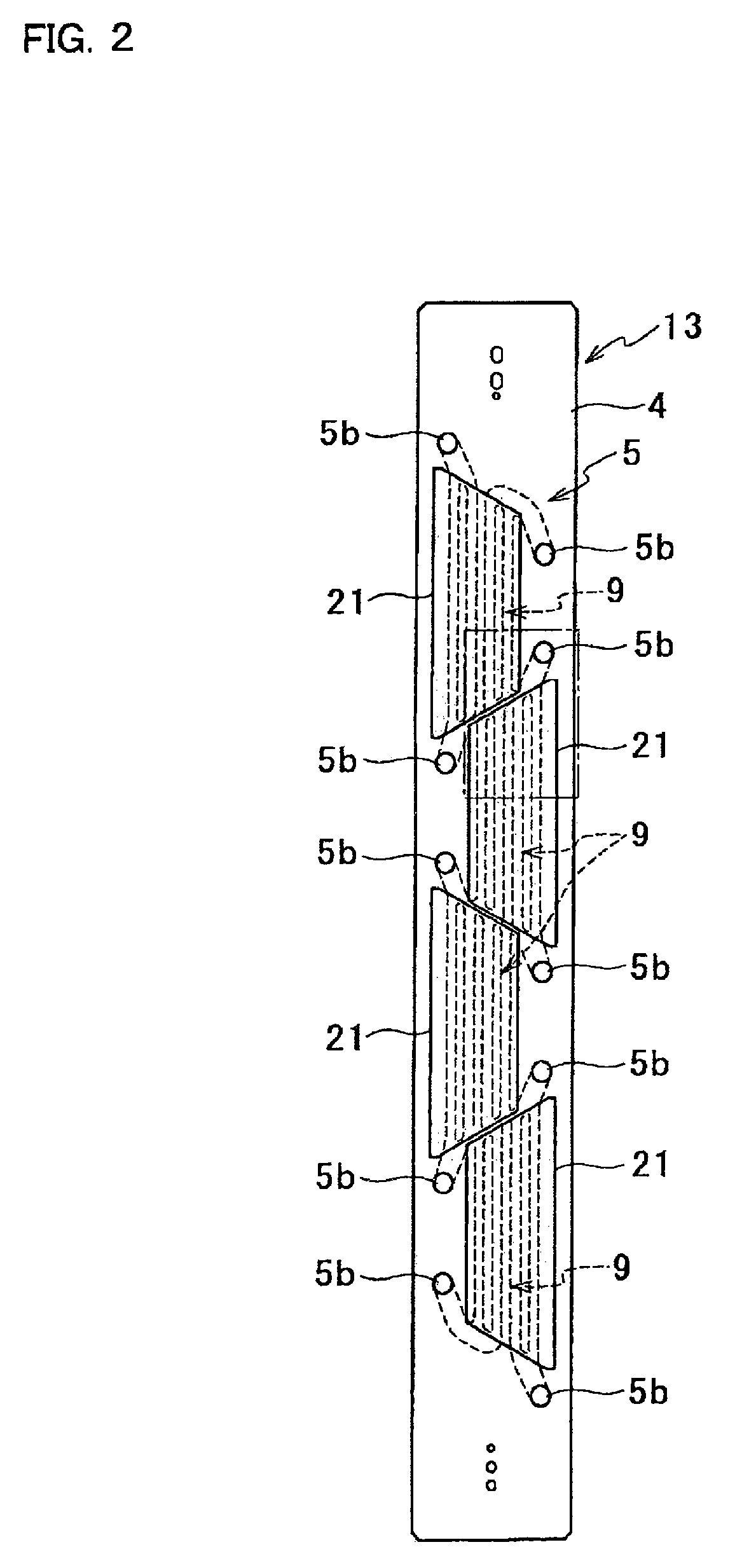
[0027]FIG. 1 shows a general construction of a color inkjet printer including inkjet heads according to an embodiment of the present invention. The printer 1 includes therein four inkjet heads 2. The inkjet heads 2 are fixed to the printer 1 in a state of being arranged in the direction of conveyance of printing papers P. Each inkjet head 2 has a slender profile extending perpendicularly to FIG. 1.

[0028]The printer 1 includes therein a paper feed unit 114, a conveyance unit 120, and a paper receiving unit 116 provided in this order along the conveyance path for printing papers P. The printer 1 further includes therein a controller 100 that controls the operations of components and units of the printer 1, such as the inkjet heads 2 and the paper feed unit 114.

[0029]The conveyance unit 120 includes an endless conveyor belt 111 and two belt rollers 106 and 107. The conveyor belt 111 is wrapped on the belt rollers 106 and 107. The length of the conveyor be...


PUM


Abstract

An inkjet head includes a passage unit and an actuator unit. The passage unit includes a common ink chamber and an individual ink passage leading from an outlet of the common ink chamber through a pressure chamber to an ejection port. The actuator unit can selectively take a first state in which the volume of the pressure chamber is V1 and a second state in which the volume of the pressure chamber is V2 larger than V1. The actuator unit changes from the first state into the second state and then returns to the first state to eject ink from the ejection port. The individual ink passage is formed such that the volume Vd of a partial passage in the individual ink passage corresponding to a region from an outlet of the pressure chamber to the ejection port, and the volume Vc of the individual ink passage, satisfy a condition that Vd / Vc is not less than 0.12 and not more than 0.40.

Description

BACKGROUND OF THE INVENTION[0001]1. Field of the Invention[0002]The present invention relates to an inkjet head that ejects ink from ejection ports.[0003]2. Description of Related Art[0004]An inkjet head that ejects ink by an inkjet system includes nozzles for ejecting ink, a common ink chamber for supplying ink to be ejected from the nozzles, and individual ink passages leading from outlets of the common ink chamber to the ejection ports of the respective nozzles. In the inkjet head, part of each individual ink passage is formed into a pressure chamber. An actuator is provided for each pressure chamber to change the volume of the pressure chamber. An ejection pulse as a voltage signal is given to the actuator to deform the actuator. Due to the deformation of the actuator, pressure is applied to ink in the pressure chamber. As a result, ink is ejected from the corresponding nozzle. At this time, the pressure applied to ink in the pressure chamber induces a pressure wave, the medium ...

Claims


Application Information

Patent Timeline
Patent Type & Authority Patents(United States)
IPC IPC(8): B41J2/045
CPCB41J2/04581B41J2/04588B41J2/04591B41J2/14209B41J2202/20B41J2002/14225B41J2002/14306B41J2002/14459B41J2202/11B41J2002/14217
Inventor HIBI, MANABUSATAKE, KENICHIISHIKURA, SHIN
Owner BROTHER KOGYO KK
Features
  • R&D
  • Intellectual Property
  • Life Sciences
  • Materials
  • Tech Scout
  • Unparalleled Data Quality
  • Higher Quality Content
  • 60% Fewer Hallucinations
Learn More