Puncture device

a puncture device and tip technology, applied in the field of puncture devices, can solve the problems of inability to efficiently absorb medical agents, difficulty in inserting the tip portion of the puncture device,

Inactive Publication Date: 2009-11-03
TERUMO KK
View PDF18 Cites 5 Cited by
  • Summary
  • Abstract
  • Description
  • Claims
  • Application Information

AI Technical Summary

Benefits of technology

[0058]According to the present invention, it is possible for a puncture needle to reach a predetermined region certainly after being stuck from a skin.
[0059]Also, according to the present invention, it is possible by means of an indwelling device to inject a medical agent to a predetermined region of a skin certainly and also, it is possible to detect a predetermined substance in the skin.

Problems solved by technology

Accordingly, it is difficult to insert a tip portion of the puncture device, for example, a needlepoint of the puncture needle accurately to the dermis which exists between the epidermis and the subcutis and if the needlepoint is inserted erroneously to the subcutis or the like, there occurs a problem such that a medical agent cannot be absorbed efficiently.

Method used


Image

  • Puncture device
  • Puncture device
  • Puncture device

Examples


first exemplified embodiment

[0071]First, it will be explained with respect to a first exemplified embodiment of a puncture device of the present invention.

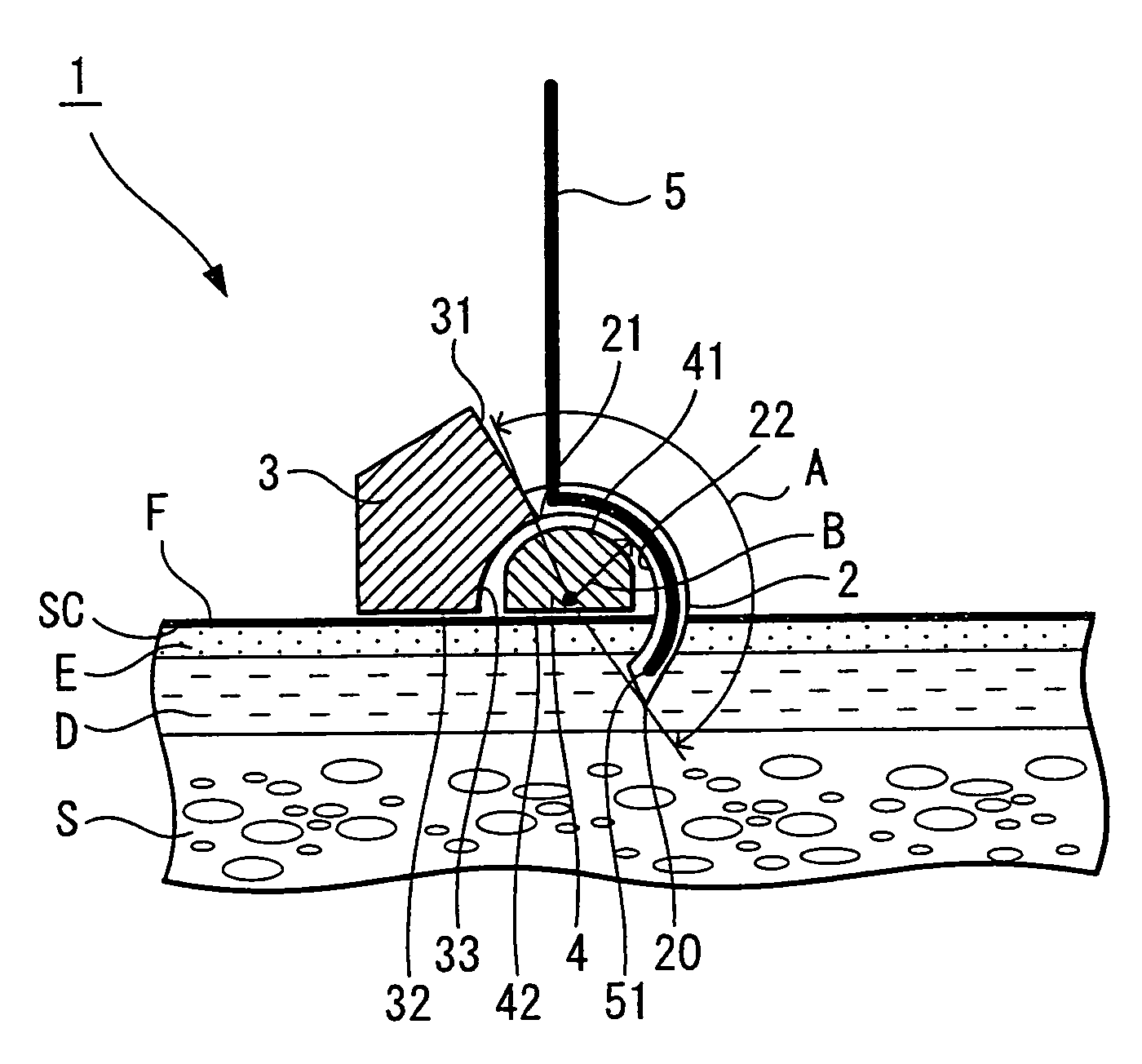
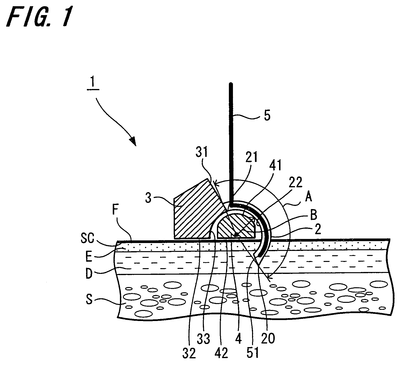
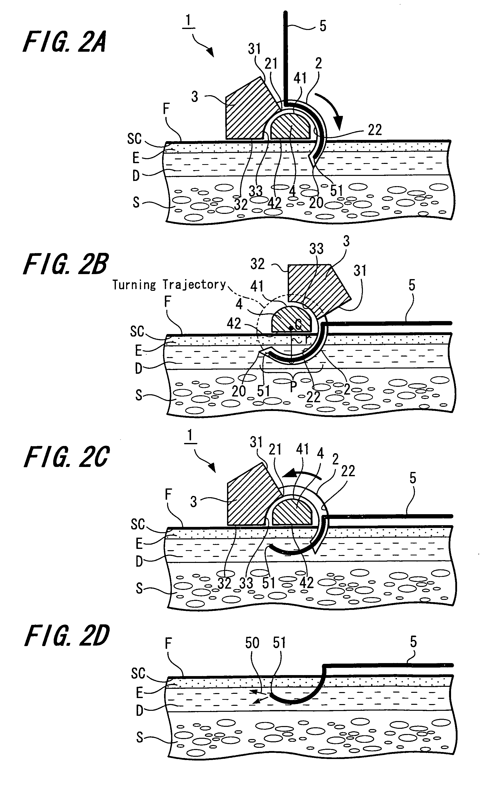
[0072]FIG. 1 shows a vertical cross-sectional view showing a first exemplified embodiment of a puncture device of the present invention. Also, FIGS. 2A-2D are diagrams (vertical cross-sectional views) for explaining the usage of the puncture device shown in FIG. 1. It should be noted that it will be explained hereinafter on an assumption that the upside in FIG. 1 and FIG. 2 is made to be “rear end” and the downside thereof is made to be “tip”.

[0073]A puncture device 1 shown in FIG. 1 has a puncture needle 2, a retaining member 3 retaining the puncture needle 2, a guide member 4 and a catheter (indwelling device) 5 inserted into the puncture needle 2.

[0074]The puncture needle 2 is a hollow needle which has a hollow portion inside and there are formed with a needlepoint 20 at the tip thereof and a coupling portion 21 being interlinked with the retaining member...

second exemplified embodiment

[0108]Next, it will be explained with respect to a second exemplified embodiment of a puncture device of the present invention.

[0109]FIG. 3 is a vertical cross-sectional view showing a second exemplified embodiment of a puncture device of the present invention. Also, FIGS. 4A-4D are diagrams (vertical cross-sectional views) for explaining the usage of the puncture device shown in FIG. 3. It should be noted that it will be explained hereinafter on an assumption that the upside in FIG. 3 and FIG. 4 is made to be “rear end” and the downside thereof is made to be “tip”.

[0110]Hereinafter, it will be explained with respect to the puncture device of the second exemplified embodiment centering on differences from the puncture device of aforesaid first exemplified embodiment and with respect to similar matters, the explanations thereof will be omitted.

[0111]The puncture device 1 of the second exemplified embodiment is provided with a fixing member 6 for fixedly retaining the catheter 5 so a ...

third exemplified embodiment

[0127]Next, it will be explained with respect to a third exemplified embodiment of a puncture device of the present invention.

[0128]FIG. 5 is a vertical cross-sectional view of a setting device 9 and a disposable cassette 10 constituting a puncture device 1 of this exemplified embodiment. Also, FIGS. 6A-6D are diagrams (vertical cross-sectional views) for explaining the usage of the puncture device shown in FIG. 5. It should be noted that it will be explained hereinafter on an assumption that the upside in FIG. 5 is made to be “rear end” and the downside thereof is made to be “tip”.

[0129]The setting device 9 as a device main body shown in FIG. 5 is constituted by an outer frame 91, a lever 92 mounted on the outer frame 91 to be movable, an elastic member 93 mounted on the lever 92, a pair of rollers 94 provided in the inside of the outer frame 91 and retained therein to be rotatable, and a belt 95 winded around these pair of rollers 94.

[0130]The setting device 9 is formed with a mou...


PUM


Abstract

A puncture device which can stick a puncture needle certainly to a predetermined region of a skin includes a puncture needle having a curvature portion, a retaining member retaining the puncture needle, an indwelling device adapted to be indwelled in a living body by way of the puncture needle, and a guide member mounted at a predetermined position of a body surface. The puncture needle is adapted to be stuck into the skin along the guide member.

Description

TECHNICAL FIELD[0001]The present invention relates to a puncture device and more specifically relates to a puncture device which punctures from a skin surface and is used with respect to a predetermined region, for example, a dermis.BACKGROUND ART[0002]It is known that the dermis has a high density of capillary blood vessels when compared with an epidermis or a subcutis and also a lymph vessel end exists therein, so that in particular, a medical agent injected thereto directly is shifted to a blood vessel or a lymph vessel and an absorption speed thereof being absorbed in the body fluid is speedy. In particular, it is possible in the dermis to make a medical agent using a macromolecular substance such as hormone, antibody drug, cytokine and the like to be absorbed into the blood efficiently. Also, it is known that the dermis is a place of efficient immunity and it is possible to make a saving of applied dose of vaccine or to strengthen sensitization of a weak vaccine.[0003]Also, it ...

Claims


Application Information

Patent Timeline
Patent Type & Authority Patents(United States)
IPC IPC(8): A61M5/178A61M5/32
CPCA61B17/3403A61M5/158A61M5/329A61B17/34A61B2017/3407A61M5/3287A61M2005/342A61M5/46A61M2005/1585A61M2005/3289A61M2005/341
Inventor SONODA, YUTAROKAWANISHI, TETSURO
Owner TERUMO KK
Why Eureka
Try Eureka