Vane-type cam phaser having bias spring system to assist intermediate position pin locking

a technology of bias springs and camshafts, which is applied in the direction of couplings, machines/engines, mechanical equipment, etc., can solve the problems of unreliable locking, unacceptably high rate of locking failure, and rotors becoming slightly cocked within, so as to increase the reliability of locking

Active Publication Date: 2009-11-10
DELPHI TECH IP LTD
View PDF12 Cites 18 Cited by
  • Summary
  • Abstract
  • Description
  • Claims
  • Application Information

AI Technical Summary

Benefits of technology

[0011]A pre-loaded bias spring system disposed on the phaser cover plate urges the rotor toward the locking position from any rotational position retarded of the locking position. When the rotor is moving in a phase-advance direction, at or near the rotor locking position the bias spring system becomes disengaged from the rotor. When the rotor is moving in a phase-retard direction, at or near the rotor locking position the bias spring system is engaged, causing the rotor to decelerate and thereby increasing the reliability of locking.
[0012]Two embodiments of such a bias spring system are presented, one comprising a torsion spring and the other comprising a pair of compression springs. In each embodiment, the phaser may be assembled without having the spring system coupled to the rotor, thereby overcoming the rotor cocking problem inherent in prior art phasers and assuring reliable mounting of an assembled phaser onto a camshaft during engine assembly.

Problems solved by technology

A known problem in such phasers is that there is no mechanical means such as a stop to assist in positioning the rotor for locking in an intermediate position; thus, locking is not reliable, and an unacceptably high rate of locking failures may occur.
Further, in prior art phasers, the torsion spring may generate an unwanted torque on the rotor about an axis orthogonal to the rotor axis, causing the rotor to become slightly cocked within the stator chamber before the phaser is installed onto the end of a camshaft during engine assembly.

Method used


Image

  • Vane-type cam phaser having bias spring system to assist intermediate position pin locking
  • Vane-type cam phaser having bias spring system to assist intermediate position pin locking
  • Vane-type cam phaser having bias spring system to assist intermediate position pin locking

Examples


Embodiment Construction

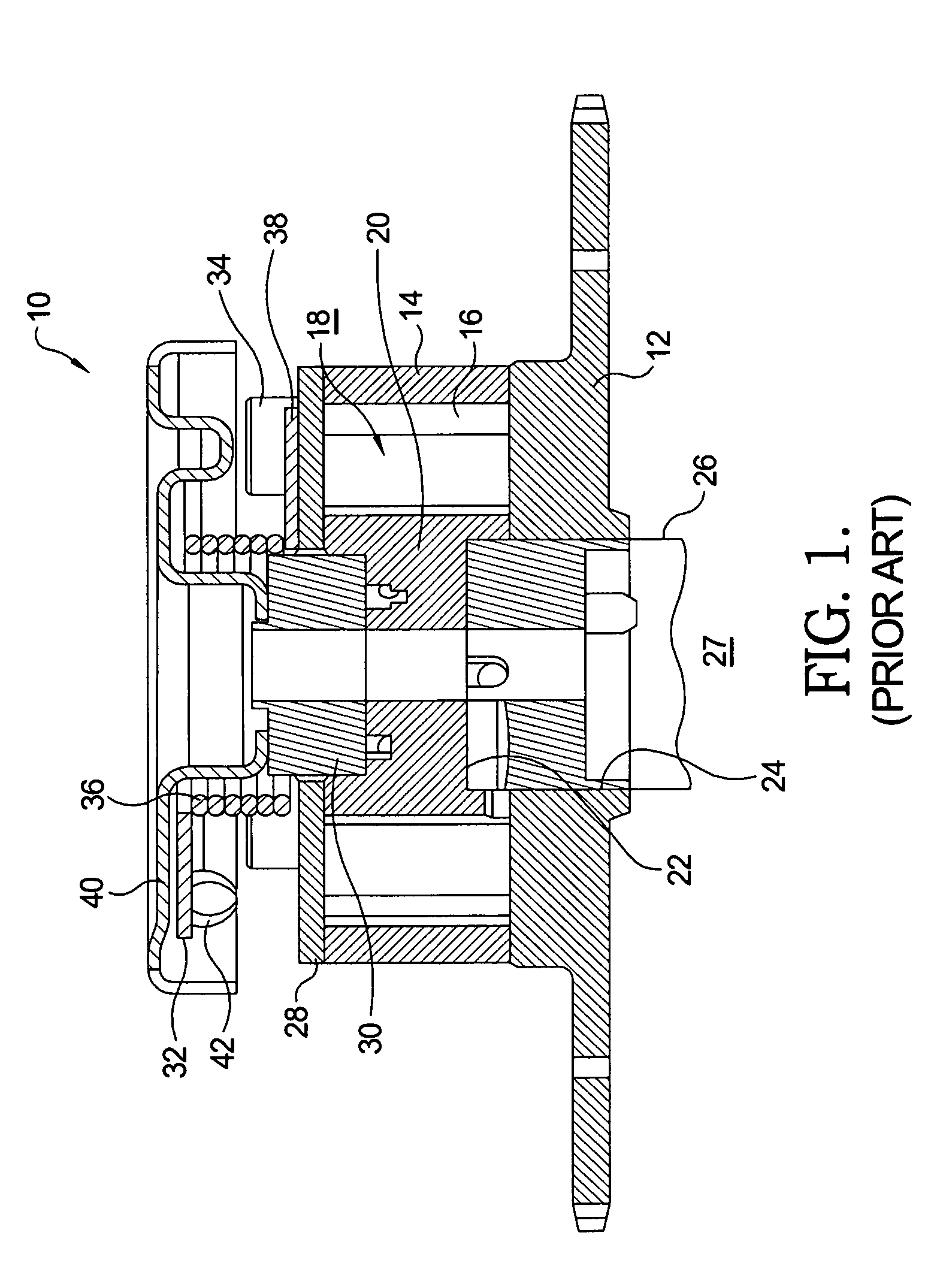
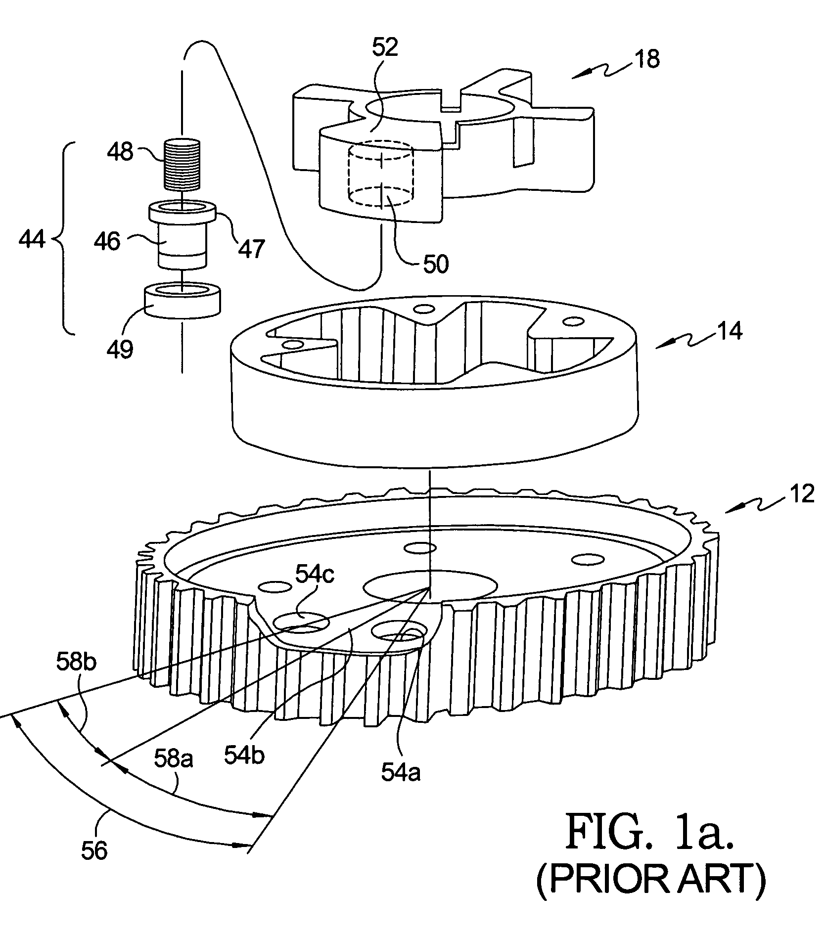
[0021]Referring to FIG. 1, a typical prior art vane-type camshaft phaser 10 includes a pulley or sprocket 12 for engaging a timing chain or belt (not shown) operated by an engine crankshaft (not shown). A stator 14 is disposed against pulley / sprocket 12 and is rotationally immobilized with respect to pulley / sprocket 12. Stator 14 is provided with a central chamber 16 for receiving a rotor 18 having a hub 20. Hub 20 is provided with a recess 22 that is coaxial with a central bore 24 in pulley / sprocket 12, allowing access of an end of engine camshaft 26 into rotor hub 20 during mounting of phaser 10 onto an internal combustion engine 27 during assembly thereof. Central chamber 16 is closed by a cover plate 28, forming advance and retard chambers between the rotor and the stator in chamber 16. A rotor hub extension 30 is pressed into a recess in rotor hub 20 and extends rotatably through a central opening in cover plate 28. A target wheel 32 is mounted onto rotor hub extension 30 by an...


PUM


Abstract

A vane-type camshaft phaser for varying the timing of combustion valves in an internal combustion engine includes a seat formed in the sprocket at the appropriate position of intermediate rotation and a locking pin slidably disposed in a vane of the rotor for engaging the seat to lock the rotor at the intermediate position. A bias spring system disposed on a cover plate urges the rotor toward the locking position from any position retarded of the locking position. A first spring system embodiment comprises a pair of compression spring assemblies. A second spring system embodiment comprises an internal torsion spring. In each embodiment, the phaser may be assembled without having the spring system coupled to the rotor, thereby overcoming a rotor cocking problem inherent in prior art phasers, assuring reliable mounting of an assembled phaser onto an engine camshaft.

Description

TECHNICAL FIELD[0001]The present invention relates to vane-type camshaft phasers for varying the phase relationship between crankshafts and camshafts in internal combustion engines; more particularly, to such phasers wherein a locking pin assembly is utilized to lock the phaser rotor with respect to the stator at certain times in the operating cycle; and most particularly, to a phaser having a bias spring system to assist in locking a phaser rotor at a rotational position intermediate between full phaser advance and full phaser retard positions.BACKGROUND OF THE INVENTION[0002]Camshaft phasers for varying the phase relationship between the crankshaft and a camshaft of an internal combustion engine are well known. A prior art vane-type phaser generally comprises a plurality of outwardly-extending vanes on a rotor interspersed with a plurality of inwardly-extending lobes on a stator, forming alternating advance and retard chambers between the vanes and lobes. Engine oil is supplied vi...

Claims


Application Information

Patent Timeline
Patent Type & Authority Patents(United States)
IPC IPC(8): F01L1/34
CPCF01L1/022F01L1/3442F01L1/024F01L2001/34463F01L2820/041F01L2001/34483F01L2103/00F01L2103/01F01L2800/01F01L2001/34469F01L2303/00F01L2303/01
Inventor FISCHER, THOMAS H.BORRACCIA, DOMINIC
Owner DELPHI TECH IP LTD
Why Eureka
Try Eureka