Smoke stick gripper

a gripper and stick technology, applied in the field of stick grippers, can solve the problems of not hanging properly downwards, complicated automation of charging and removal,

Active Publication Date: 2009-11-10
ALBERT HANDTMANN MASCHFABRICK
View PDF13 Cites 16 Cited by
  • Summary
  • Abstract
  • Description
  • Claims
  • Application Information

AI Technical Summary

Benefits of technology

[0007]Based on this, the object of the present disclosure is to provide a method and a gripper system which facilitate in a simple and reliable manner the automated gripping and transferal of a smoke stick.
[0008]According to the present disclosure, the smoke stick, which is positioned already under the hooks between the suspended products, is firmly gripped by at least two grippers, wherein the grippers hold and fix the smoke stick during the removal. Here, fixing is taken to mean that the gripper holds the smoke stick firmly such that it cannot move about its longitudinal axis or in the longitudinal direction. This facilitates a high handling speed without the smoke stick slipping in the gripper. Moreover, the method according to the disclosure facilitates the alignment of the smoke stick and the products hanging on it by rotation of the smoke stick about its longitudinal axis. As already explained, during the removal of the products suspended on the hooks, the products may not hang properly downwards, but instead lie somewhat obliquely on the smoke stick. By rotating the smoke stick about its longitudinal axis L, the smoke stick and the products can be aligned such that for example the twist-off point between two sausages comes to rest at the upper end of a smoke stick, advantageously on a tip of a smoke stick with a star-shaped contour. Due to the force of gravity acting on the sausage loops, the sausages align themselves automatically so that they hang downwards. The smoke stick can then be transported to a smoke stick depository, for example with a handling system or robot arm, wherein the smoke stick is here fixed in the grippers. The fixing facilitates a high handling speed without slippage of the smoke stick. Finally, the smoke stick is deposited on a smoke stick depository, in particular on a smoke stick depository of a smoke trolley.
[0009]According to the present disclosure, in step b) the fixing of the smoke stick is released so that the smoke stick can be rotated about its longitudinal axis and moved in its longitudinal direction in the grippers so that the smoke stick is aligned automatically by the force of gravity of the suspended products. Thus, in a simple manner the automatic downward alignment of the products or of the pairs or loops of sausages is facilitated without an additional drive. Thus, reliable removal of the sausage loops from the hanger is possible in which the smoke stick and the products suspended from it are automatically aligned by the force of gravity on the sausage loops. Thus, the sausage loops can be accurately suspended at the twist-off points which reduces possible pressure points.

Problems solved by technology

As already explained, during the removal of the products suspended on the hooks, the products may not hang properly downwards, but instead lie somewhat obliquely on the smoke stick.
This is particularly important because many smoke trolleys have tolerance errors which render the automation of charging and removal very complicated.

Method used


Image

  • Smoke stick gripper
  • Smoke stick gripper
  • Smoke stick gripper

Examples


second embodiment

[0046]FIGS. 8a and b illustrate a gripper system according to the present disclosure, which essentially corresponds to the embodiment illustrated in connection with FIGS. 3a and 3b, wherein however the gripper 1 has an additional pivot axis A, which essentially runs parallel to the longitudinal axis of the smoke stick 2 so that the gripper can be pivoted (refer to FIG. 8b) about the pivot axis A in the closed position (refer to FIG. 8a) in which it holds and fixes the smoke stick 2. Due to the fact that the smoke stick 2 is pivoted with the gripper, a relative rotation of the smoke stick 2 about its longitudinal axis L is produced, as is clear in particular on comparison of the FIGS. 8a and 8b. This rotation can be used effectively for the alignment of the smoke stick and the products which are suspended on it as is explained in more detail in the following in connection with the method according to the disclosure. With this embodiment illustrated in FIG. 8 the gripper system, which...

first embodiment

[0048]In the following the method according to the disclosure is explained in more detail in conjunction with the FIGS. 1 to 3.

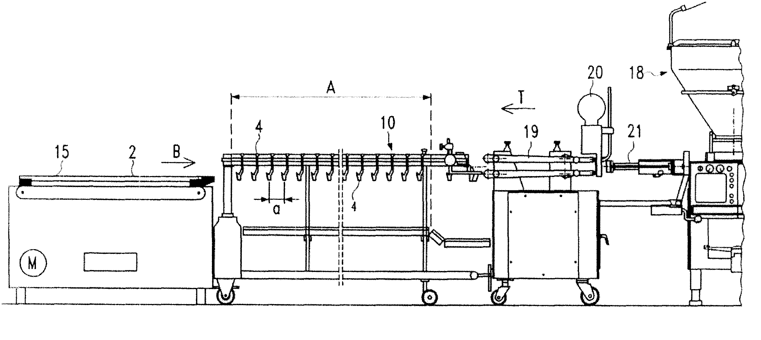
[0049]Before the method according to the disclosure, as previously explained, the products are suspended in pairs or in loops on the hooks 4, as illustrated in FIG. 7, and the smoke stick 2 is introduced in the receiving region A of the hanger 10 between the suspended products with the aid of the device 15.

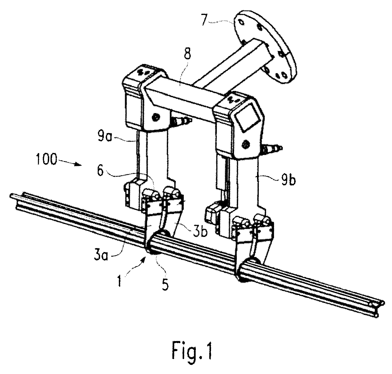
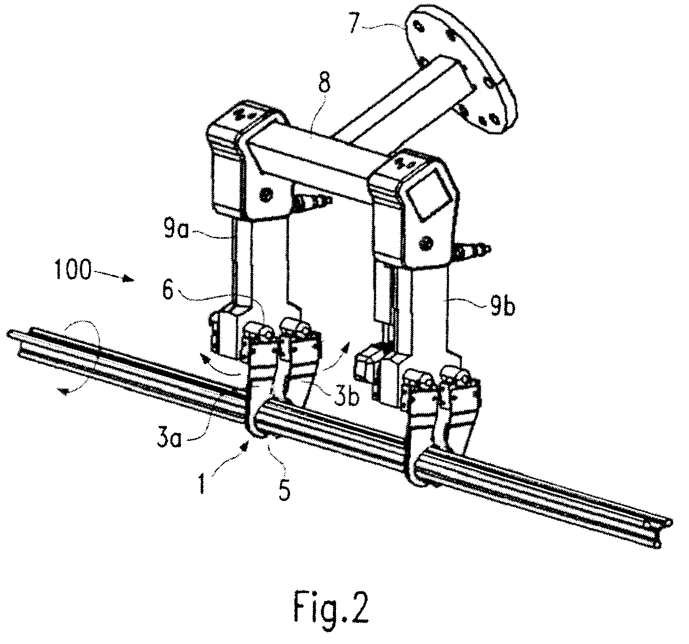
[0050]The robot arm 16 then moves the grippers of the gripper system 100 either from above (refer to arrows G in FIG. 7) or however from the side between the suspended products or between the hooks 4 above or next to the smoke stick and closes the grippers such that they hold and fix the smoke stick 2, as illustrated for example in FIGS. 1 and 3a. The introduction can take place with closed grippers in order not to damage the products.

[0051]Preferably, at least one gripper 1 here grips in the central smoke stick region. Since the grippers 1 are, as previou...


PUM


Abstract

A gripper system for gripping and transferring a smoke stick introduced into sausage loops or into other products suspended on hooks in loops or in pairs. For the simple and proper gripping and transferal of a smoke stick a smoke stick is first lifted to remove the products from the hooks with at least two grippers, wherein the grippers grip the smoke stick between the hooks, wherein the grippers hold and fix the smoke stick during removal. The smoke stick and the products suspended from it are then aligned by rotation of the smoke stick about its longitudinal axis. The smoke stick is then transported to a smoke stick depository, wherein the smoke stick is fixed in the grippers and then deposited on a smoke stick depository.

Description

CROSS-REFERENCE TO RELATED APPLICATION[0001]The present application claims the benefit of priority of European Patent Application No. EP 07010524.2, filed May 25, 2007. The entire text of the priority application is incorporated herein by reference in its entirety.FIELD OF THE DISCLOSURE[0002]The disclosure relates to a method of gripping and transferring a smoke stick introduced into products, in particular sausages, hung in loops or in pairs on hooks as well as an appropriate gripper system.BACKGROUND[0003]During the industrial manufacture of sausages, the produced products are transferred directly from the filling machine onto a hanger. The pairs or loops of sausages are here preferably hung at the portioning point between two sausages on a hook. The sausages are then manually taken up with a smoke stick. This is then hung in a smoke trolley by the operator. The smoke trolley is then in turn pushed into a smoke chamber. The wide variety of different smoke sticks, smoke trolleys a...

Claims


Application Information

Patent Timeline
Patent Type & Authority Patents(United States)
IPC IPC(8): A22C15/00
CPCA22C15/007A22C15/001
Inventor LIERMANN, TORSTENFUCHS, MARKUSMAYER, STEFFENABELE, BENJAMIN
Owner ALBERT HANDTMANN MASCHFABRICK
Why Eureka
Try Eureka