Supercharge Your Innovation With Domain-Expert AI Agents!

Optical apparatus

a technology of optical equipment and optical sensors, applied in the field of optical equipment, can solve the problems of inability to achieve focus, inability to achieve satisfactory in-focus accuracy, and favorable af performance, and achieve the effect of favorable af control and high in-focus accuracy

Inactive Publication Date: 2009-11-10
CANON KK
View PDF12 Cites 1 Cited by
  • Summary
  • Abstract
  • Description
  • Claims
  • Application Information

AI Technical Summary

Benefits of technology

This approach achieves both high in-focus accuracy and favorable responsiveness in high-definition image pickup systems by selectively using the characteristics of low and high-frequency AF evaluation signals, preventing focus on background elements and ensuring the main subject is sharply focused.

Problems solved by technology

In the camera capable of picking up images in the high-definition system, however, the following problems occur when the AF control is performed by using the AF evaluation value signal in the same frequency band as that in the standard TV system.
With the difference in the resolution spatial frequency, it is possible that the AF evaluation value signal in the ‘NTSC’ (Hz) is used for AF control in the high-definition image pickup but focus cannot be achieved.
However, if the AF evaluation value signal in the ‘NTSC’ (Hz) is used in the high-definition image pickup, satisfactory in-focus accuracy may not be realized since the ΔNTSC range is wider than the ΔHD range.
However, constantly adding the AF evaluation value signal in the ‘NTSC’ (Hz) to the AF evaluation value signal in the ‘HD’ (Hz) during AF control may not result in favorable AF performance.
This reduces the responsiveness in AF.
In this manner, only the AF evaluation value signal in the low frequency band for the NTSC system cannot provide in-focus accuracy suitable for the high-definition system.
In addition, simply synthesizing the AF evaluation value signal for the high-definition system and the AF evaluation value signal for the NTSC system to provide in-focus accuracy necessary for the high definition may make it difficult to focus on the major subject to reduce the responsiveness.

Method used


Image

  • Optical apparatus
  • Optical apparatus
  • Optical apparatus

Examples


embodiment 1

[0040]In Embodiment 1, an AF evaluation value signal in a high frequency band as a high-definition frequency band and an AF evaluation value signal in a low frequency band as an NTSC frequency band are synthesized (added) to provide a synthesis AF evaluation value signal for use in AF control. However, the synthesis which accentuates the characteristic of the AF evaluation value signal in the high frequency band is not always performed during AF control but is performed after a focusing operation to near an in-focus point using the AF evaluation value signal in the low frequency band, thereby achieving focusing with higher accuracy.

[0041]First, the general outlines of Embodiment 1 will be described with reference to FIGS. 12A to 12D, 13A to 13D, and 10A. As described above, FIGS. 12A and 13A show the examples in which the person as the major subject is at the center of the frame, the mountain and trees are behind the person as the background, respectively, and the object is in front...

embodiment 2

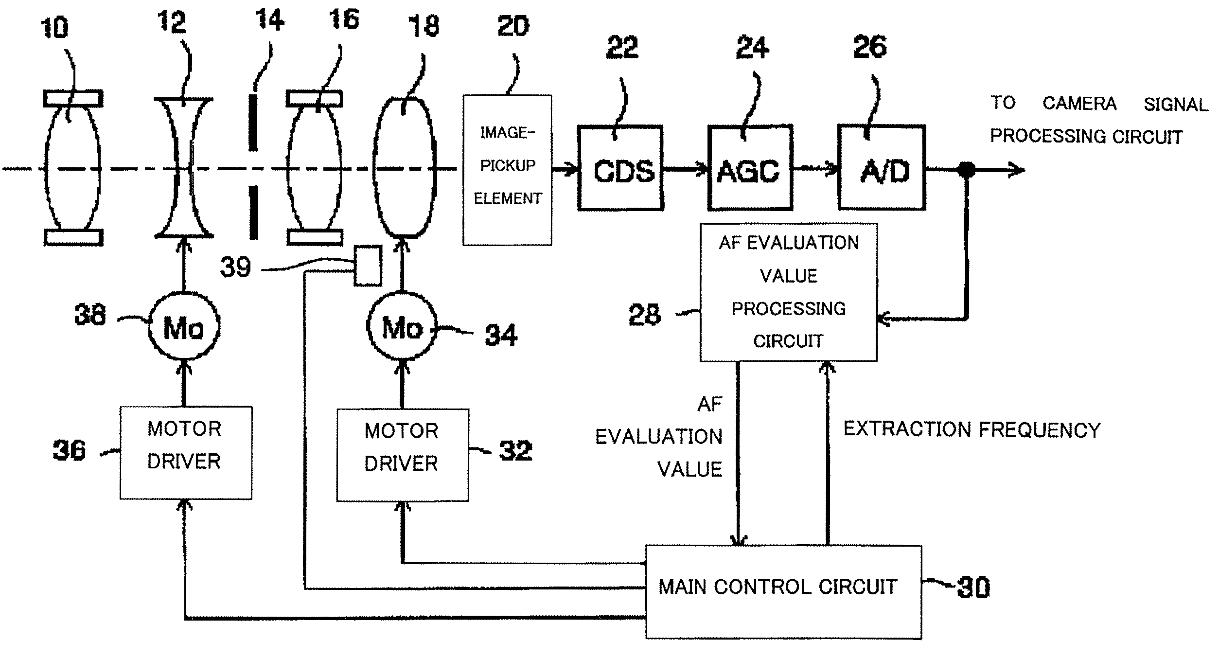
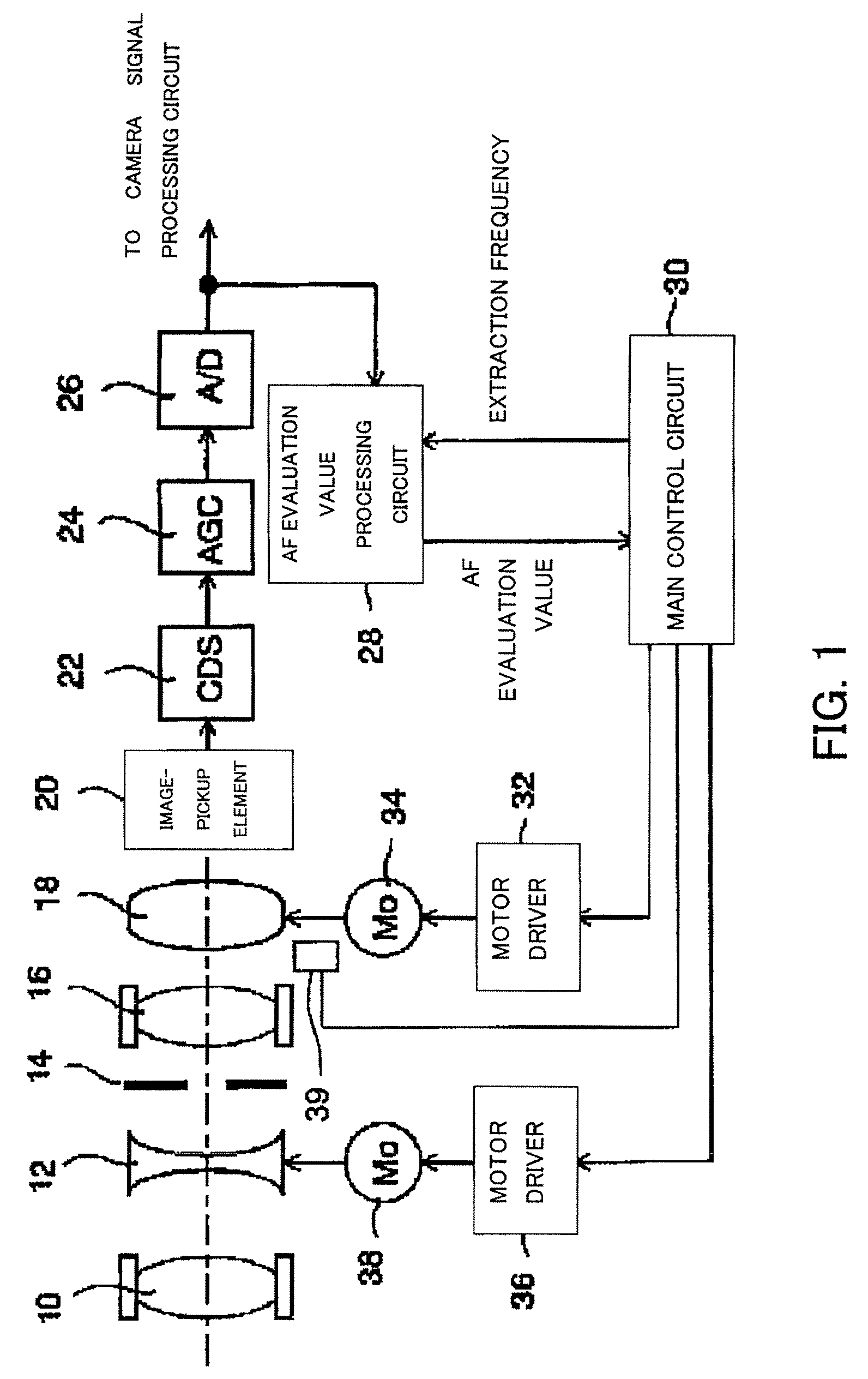
[0184]Embodiment 2 of the present invention will hereinafter be described. The basic structure of an image-pickup apparatus in Embodiment 2 is identical to the structure described with reference to FIG. 1 in Embodiment 1. Components identical to those in Embodiment 1 are designated with the same reference numerals as those in FIG. 1.

[0185]In Embodiment 2, the in-focus determination is made using the first synthesis AF evaluation value signal in the first step of minute-drive control, and then, in the second step, final in-focus determination is made using the second synthesis AF evaluation value signal. Each in-focus determination is performed on the basis of a repeat of to-and-fro movement of the focus lens 18 a predetermined number of times in the same area.

[0186]In other words, coarse in-focus determination is first made (in a wide allowable area) by confirming a repeat of to-and-fro movement a predetermined number of times using the first synthesis AF evaluation value signal con...

embodiment 3

[0211]Embodiment 3 of the present invention will hereinafter be described. FIG. 9 shows the structure of an image-pickup apparatus serving as an optical apparatus of Embodiment 3. The image-pickup apparatus is realized by a video camera or a digital still camera which are integral with a lens and its image-pickup system can be switched between the standard TV system and the high-definition system. Moving images or still images may be picked up by the apparatus. Components of the camera identical to those in Embodiment 1 are designated with the same reference numerals as those in Embodiment 1 and the description thereof is omitted.

[0212]In FIG. 9, reference numeral 40 shows an image-pickup system selecting switch for allowing an operator to select image pickup in the standard TV system such as NTSC and PAL or image pickup in the high-definition system. In other words, the switch 40 is provided for setting the resolution of images to be picked up. When the switch 40 is used to select ...


PUM


Abstract

An optical apparatus is disclosed which achieves high focusing accuracy and favorable responsiveness in AF control. The apparatus includes a signal generator which extracts signals in a plurality of frequency bands from an output from an image-pickup part and generates focus signals from the extracted signals, and a controller which performs focus control such that the focus signal approaches the highest value. The controller uses a first focus signal and a second focus signal in the focus control. The second focus signal is a synthesis signal formed by synthesizing a focus signal in a relatively high or the highest frequency band of the plurality of frequency bands and a focus signal in another frequency band and contains a component of the focus signal in the relatively high or highest frequency band at a higher ratio as compared with the first focus signal.

Description

BACKGROUND OF THE INVENTION[0001]The present invention relates to a technique of auto-focus (AF) control in an optical apparatus such as a video camera, a digital still camera, and an interchangeable lens apparatus.[0002]An AF function provided for optical apparatuses is realized by generating a focus signal (hereinafter referred to as an AF evaluation value signal) representing the sharpness of video image from a video signal generated by an image-pickup part including an image-pickup element and then controlling drive of a focus lens such that the AF evaluation value signal is at the maximum. Such an AF method is called a contrast AF method or a TV-AF method.[0003]The AF evaluation value signal is typically generated on the basis of high-frequency components extracted from the video signal through a band-pass filter (BPF). When an image is blurred, the high-frequency components, that is, the AF evaluation value signal is at a low level. As the image is brought into an in-focus sta...

Claims


Application Information

Patent Timeline
Patent Type & Authority Patents(United States)
IPC IPC(8): H04N5/232G03B13/00
CPCH04N5/23212G03B13/36H04N23/673
Inventor OHTA, SEIYA
Owner CANON KK
Features
  • R&D
  • Intellectual Property
  • Life Sciences
  • Materials
  • Tech Scout
  • Unparalleled Data Quality
  • Higher Quality Content
  • 60% Fewer Hallucinations
Learn More