Power supply controller to actively drive a load current when the load current exceeds a set point

a technology of power supply controller and load current, which is applied in the direction of power conversion system, dc-dc conversion, instruments, etc., can solve the problems of delay in sensing, high current condition may persist, and the state of the converter circuit's switch may be too long to chang

Active Publication Date: 2009-11-10
MKS INSTR INC
View PDF24 Cites 33 Cited by
  • Summary
  • Abstract
  • Description
  • Claims
  • Application Information

AI Technical Summary

Benefits of technology

[0008]Higher switching frequencies, slower sensing circuits, and slower switch drive circuits at a given switching frequency may be used in conjunction with the inventive control circuit and the switching power supply it controls. Accordingly, lower cost with better performance is achieved.
[0012]In some embodiments, the system has four switches, wherein the states of two of the switches are changed to change the current flow path. In some embodiments, the plurality of switches are configured in a switching topology selected from the group consisting of a push pull converter, a half bridge converter, and a full bridge converter. The system also can include reverse polarity diodes disposed relative to the plurality of switches to protect the switches from reverse current flow.

Problems solved by technology

With these conventional control circuits, however, the high current condition may persist after pulse termination due to a lack of load voltage to drive the current down, overheating the circuit elements.
Or, the delay in sensing the over current condition in the load and then changing the state of the converter circuit's switches may be too long.
This can slow, rather than quicken, the correction of the load current.
In particular, the load current may fail to return to zero and instead continue to have a single polarity over several switching cycles.
This can interrupt the power conversion process or destroy the converter circuit's elements.
Moreover, the resulting load current waveform may have multiple transitions, causing excessive dissipation in the switching elements.

Method used


Image

  • Power supply controller to actively drive a load current when the load current exceeds a set point
  • Power supply controller to actively drive a load current when the load current exceeds a set point
  • Power supply controller to actively drive a load current when the load current exceeds a set point

Examples


Embodiment Construction

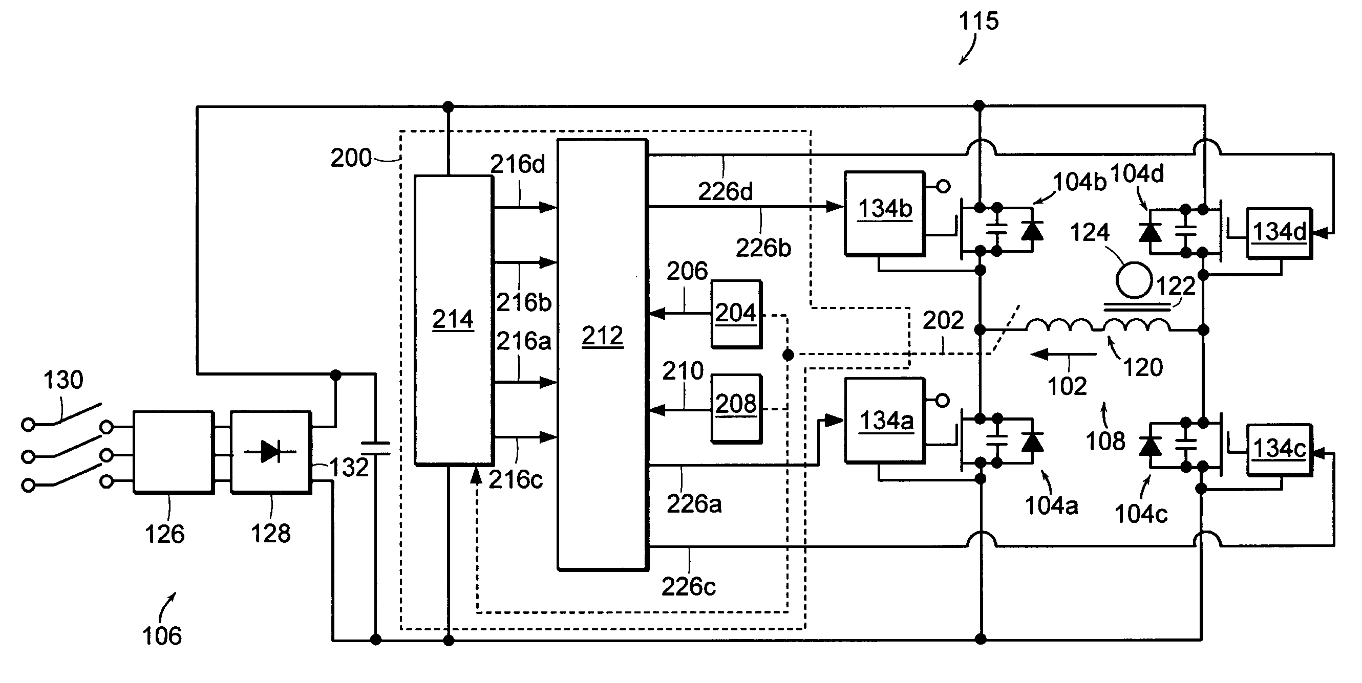
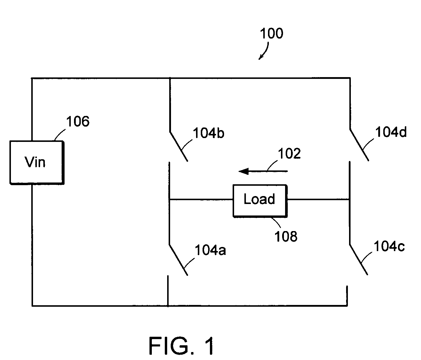
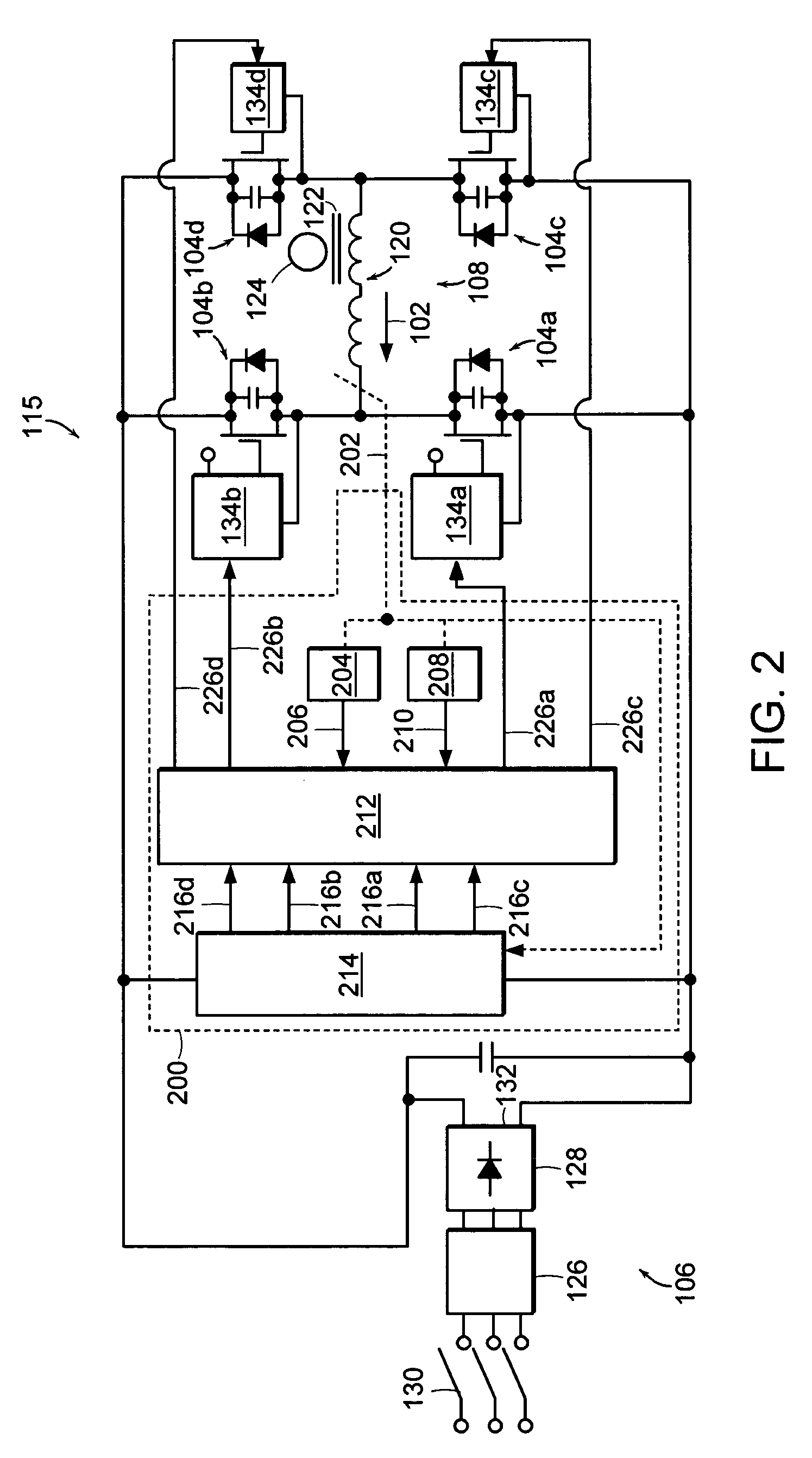
[0027]FIG. 1 depicts an exemplary switching power supply. More particularly, FIG. 1 depicts a full bridge converter circuit 100. As described herein, the full bridge converter circuit 100 is a phase modulated full bridge converter circuit 100, a common choice for high frequency applications. The phase modulated full bridge converter circuit 100 is an exemplary switching power supply for which a load current 102 can be controlled and, in the case of an over current condition, can be quickly corrected by the control circuit 200 (see FIG. 2) according to the invention. It should be noted, however, that the control circuit 200 could, with appropriate modifications, also be used to control and / or correct the load current of other converter circuits, such as, for example, a push-pull converter, a half-bridge converter, or a pulse width modulated full-bridge converter.

[0028]As illustrated in FIG. 1, the full bridge converter circuit 100 includes first, second, third, and fourth switches 10...


PUM


Abstract

A control circuit for a switching power supply reacts to an over current condition in the switching power supply to bring its operating point to a safe condition. The control circuit senses both the direction and the magnitude of the load current in the switching power supply, and then uses this sensed information to control the active power switches in the switching power supply. In an over current condition, the switches are controlled to actively drive the load current toward zero, even if the sensed information is delayed or heavily filtered, or the switch signals from the control circuit are delayed in reaching the switches. The resulting operation of the switching power supply is more resistant to abnormal load conditions and is maintained in the presence of transient short circuits or arcs. The switching power supply hardware is also better protected.

Description

RELATED APPLICATIONS[0001]This application claims priority of U.S. Provisional Application Ser. No. 60 / 552,691 filed Mar. 12, 2004.FIELD OF THE INVENTION[0002]The invention relates to methods and systems for controlling a switching power supply.BACKGROUND OF THE INVENTION[0003]A switching power supply can be implemented using conventional circuit topologies such as, for example, a push-pull converter, a half-bridge converter, a pulse width modulated full-bridge converter, or a phase modulated full-bridge converter. For each of these converter circuits, if the load current grows too large, a control circuit responds by changing the state of one or more switches in the converter circuit to limit the load current. Conventional control circuits sense only the magnitude of the load current and, if determined to be too large, terminate the active current driving pulse or shut down the converter circuit altogether.[0004]With these conventional control circuits, however, the high current co...

Claims


Application Information

Patent Timeline
Patent Type & Authority Patents(United States)
IPC IPC(8): H02M7/5387H02M1/00H02M3/335
CPCH02M7/53871H02M1/32H02M7/53846H02M7/5388
Inventor MILLNER, ALAN ROYBYSTRYAK, ILYA
Owner MKS INSTR INC
Why Eureka
Try Eureka