
Method for manufacturing a pneumatic tire and a pneumatic tire obtained thereby

a manufacturing method and technology of pneumatic tires, applied in the direction of tires, vehicle components, non-skid devices, etc., can solve the problems of unevenness of tires, cracks or rubber chippings in those portions, and it is difficult to wind the rubber strip g at specified positions in an accurate manner, so as to improve productivity, uniformity and durability.

Inactive Publication Date: 2009-11-17
SUMITOMO RUBBER IND LTD
View PDF15 Cites 1 Cited by
  • Summary
  • Abstract
  • Description
  • Claims
  • Application Information

AI Technical Summary

Benefits of technology

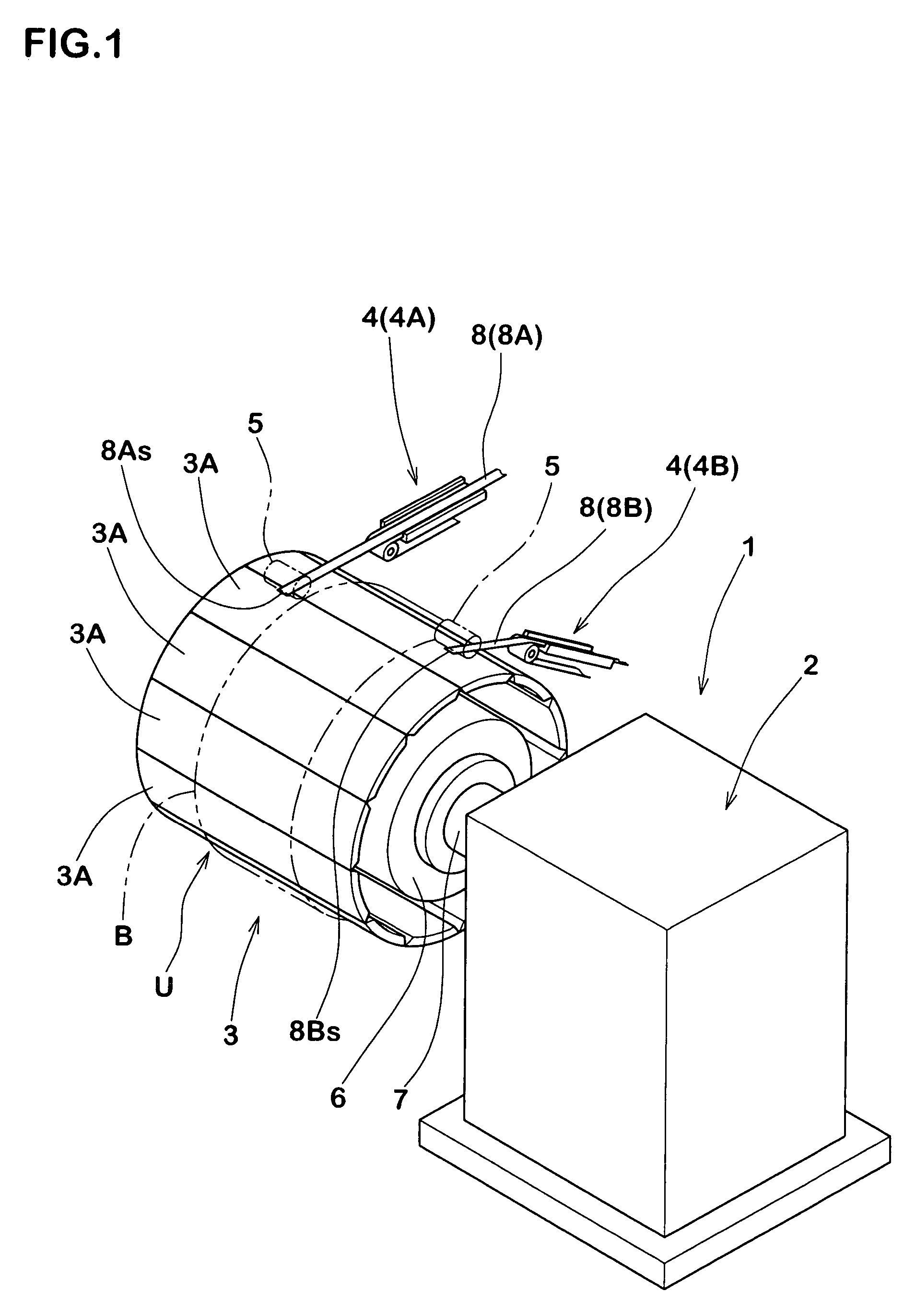
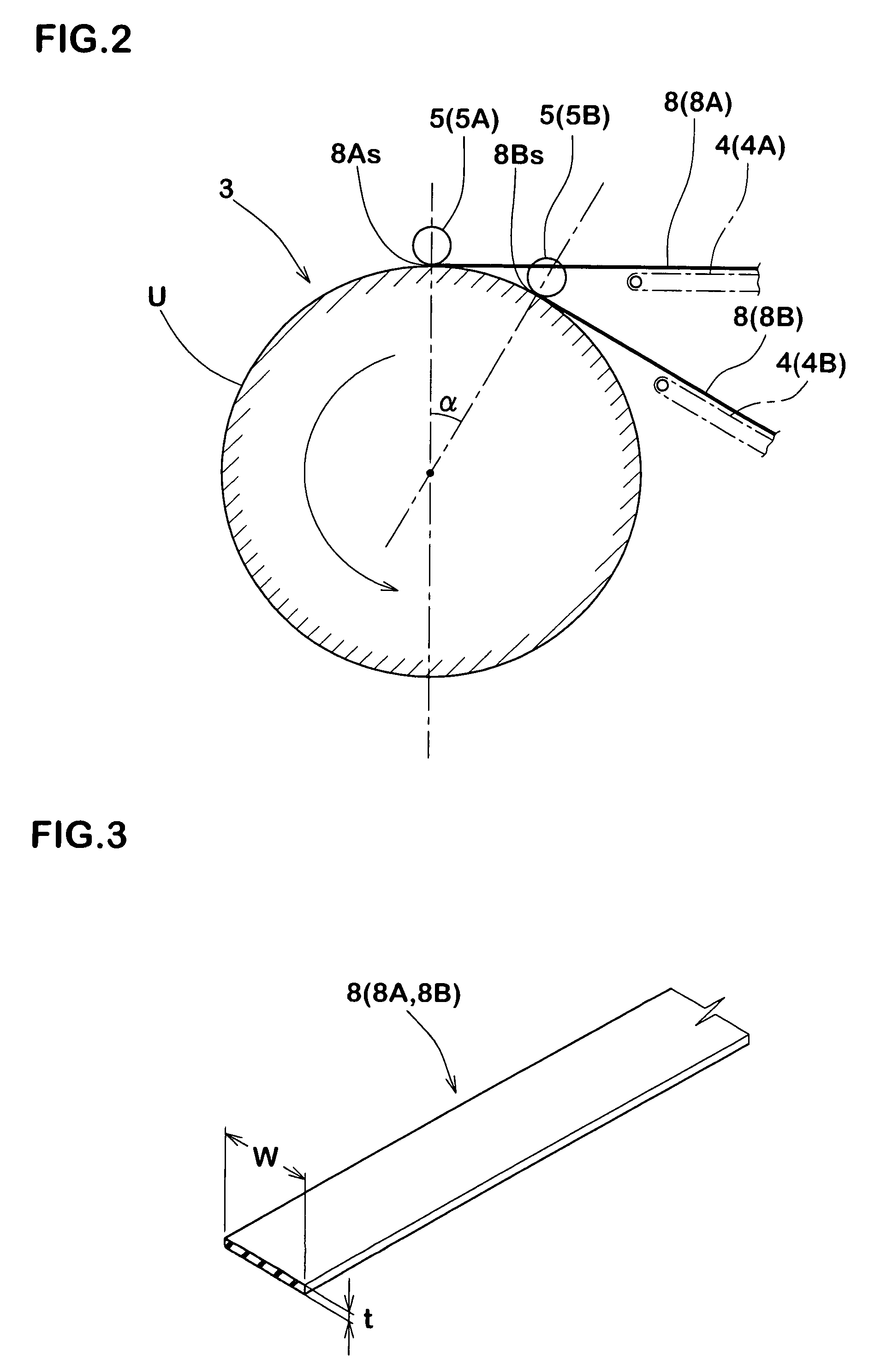
The present invention provides a method for manufacturing a pneumatic tire with improved productivity, uniformity, and durability. This is achieved by specifying the positions of winding start points and winding end points of rubber strips. The method includes a step of fixedly attaching the winding start points of the rubber strips to the tire at positions located inward in the width direction than the sides of the wound body. This arrangement ensures that the winding start points are not located at the sides of the rubber member, which improves the uniformity and durability of the tire. The method also includes a first winding step for forming a first layer by spirally winding the rubber strips towards one side and a second winding step for forming a second layer outside of the first layer by turning the rubber strips up and spirally winding them towards the other side without cutting them. This arrangement allows for the formation of a rubber member of relatively large thickness in a short time and in an efficient manner. The winding end points of the rubber strips are fixedly attached at positions inward in the width direction than the sides of the wound body, which further improves the uniformity and durability of the tire. The method also allows for the easy uniformization of the gauge through the width of the tread rubber and the efficient manufacturing of a pneumatic tire with improved uniformity and durability.

Problems solved by technology

It is accordingly the case that a stepped non-continuous portion k that comprises a corner when seen in a planar view is apt to occur between an end surface and an side of an adjoining rubber strip at the winding start point s and the winding end point f of the rubber strip g. Such non-continuous portions k lead to a drawback in that lateral sections of tread rubbers tr become non-uniform in the tire circumferential direction to thus worsen tire uniformity.
Accordingly, when those points are located at sides of the tread rubber etc, drawbacks are presented in that cracks or rubber chippings tend to occur from those portions after vulcanization.
It is difficult to wind the rubber strip g at specified positions in an accurate manner.
Due to those facts, it is difficult to adjust the thickness (gauge) of respective parts of the tread rubber tr so that irregularities are apt to occur in the sectional shape in the above-mentioned method.
Non-uniformity of gauges at end portions of the tread rubber tr (end portions of the wound body) is not desirable since they conspicuously worsen the uniformity of the tire and degrade the durability of the tire.

Method used


Image

  • Method for manufacturing a pneumatic tire and a pneumatic tire obtained thereby
  • Method for manufacturing a pneumatic tire and a pneumatic tire obtained thereby
  • Method for manufacturing a pneumatic tire and a pneumatic tire obtained thereby

Examples


examples

[0097]Twenty pneumatic tires for heavy-duty purpose of a tire size of 11R22.5R each were manufactured by using a plurality of types of non-vulcanized tread rubbers according to the specifications as illustrated in Table 1. Except the tread rubbers, tread patterns and internal structures were common to all. Uniformity and durability of the tread rubber were evaluated for all of those.

[0098]Methods of evaluation were as follows.

[0099]Radial runouts (RRO) were measured for each sample tire (average value of n=20) and indicated as indices with the RRO of the Comparative Example 1 being defined as 100. The smaller the values are, the more preferable they are.

[0100]The sample tires were attached to a rim of 7.50□22.5 and were made to run on a drum of 1.7 m radius at an air pressure of 700 kPa, a load of 50 kN and a velocity of 100 km / h over 50,000 km, and the tread rubbers were then visually observed and split after the visual observation to check internal damage conditions.

[0101]Test res...


PUM

PropertyMeasurementUnit
thicknessaaaaaaaaaa
thicknessaaaaaaaaaa
thicknessaaaaaaaaaa

Abstract

It is a subject to provide a method for manufacturing a tire rubber member and a pneumatic tire using the same capable of improving productivity and of accurately finishing sectional shapes. The method includes: a step of fixedly attaching winding start points 8As, 8Bs of a first rubber strip 8A and a second rubber strip 8B at positions located further inside in a width direction than respective sides e1, e2 of a rubber member R; a first winding step of forming a first layer 10 by spirally winding the first rubber strip 8A towards the one side e1 and the second rubber strip 8B towards the other side e2 up to the respective sides e1, e2; a second winding step of respectively turning the first rubber strip 8A up at the one side e1 and the second rubber strip 8B at the other side e2 so as to successively form a second layer 11 outside of the first layer 10; and a step of fixedly attaching a winding end point 8Af of the first rubber strip and a winding end point 8f of the second rubber strip to positions further inside in the width direction than the respective sides e1, e2.

Description

BACKGROUND OF THE INVENTION[0001]The present invention relates to a method for manufacturing a pneumatic tire including a tire rubber member of accurate sectional shape and with which it is possible to improve productivity, and to a pneumatic tire obtained thereby.[0002]There is recently suggested a strip-wind method as illustrated in FIGS. 14 to 16. In the strip-wind method, there is formed a wound body in which a ribbon-like non-vulcanized rubber strip g is spirally wound around an object c to be wound. A green tire employing such a wound body is vulcanized and molded. In this manner, the wound body can comprise a tire rubber member such as a tread rubber tr. Such strip-wind method is suggested in, for instance, Japanese Patent No. 3,477,289, Japanese Patent No. 3,352,045, Japanese Patent No. 3,370,282 and Japanese Patent No. 3,397,430. The object c to be wound onto which the rubber strip g is wound can be a shrinkable mold former of cylindrical shape or a tread portion of a green...

Claims


Application Information

Patent Timeline
Patent Type & Authority Patents(United States)
IPC IPC(8): B60C11/00B29D30/60
CPCB29D30/60B29D30/30
Inventor HAYASHI, NORIOTAKAHASHI, MASANORI
Owner SUMITOMO RUBBER IND LTD
Learn More