Strand-guiding roller

a technology of guiding rollers and guiding rollers, which is applied in the direction of mechanical equipment, manufacturing tools, and foundation moulding equipment, etc., can solve the problems of high thermal and mechanical stress, inability to replace rolls, and inability to dismantle rolls, so as to avoid the effect of deformation and wear, avoiding the effect of peak thermal and mechanical loads

a technology of guiding rollers and guiding rollers, which is applied in the direction of mechanical equipment, manufacturing tools, and foundation moulding equipment, etc., can solve the problems of high thermal and mechanical stress, inability to replace rolls, and inability to dismantle rolls, so as to avoid the effect of deformation and wear, avoiding the effect of peak thermal and mechanical loads

US7617862B2Inactive Publication Date: 2009-11-17SIEMENS VAI METALS TECHNOLOGIES GMBH & CO

Image

  • Strand-guiding roller
  • Strand-guiding roller
  • Strand-guiding roller

Examples


Embodiment Construction

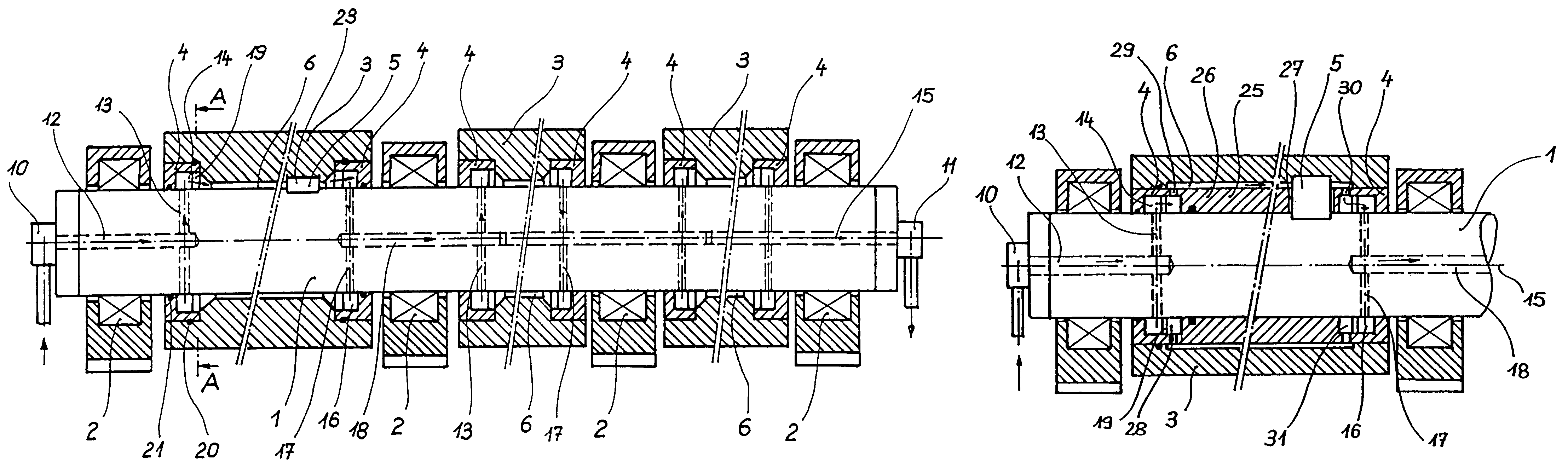
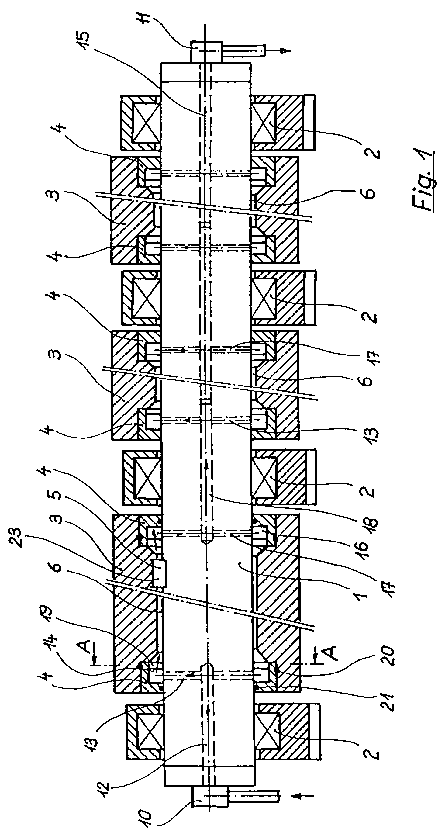
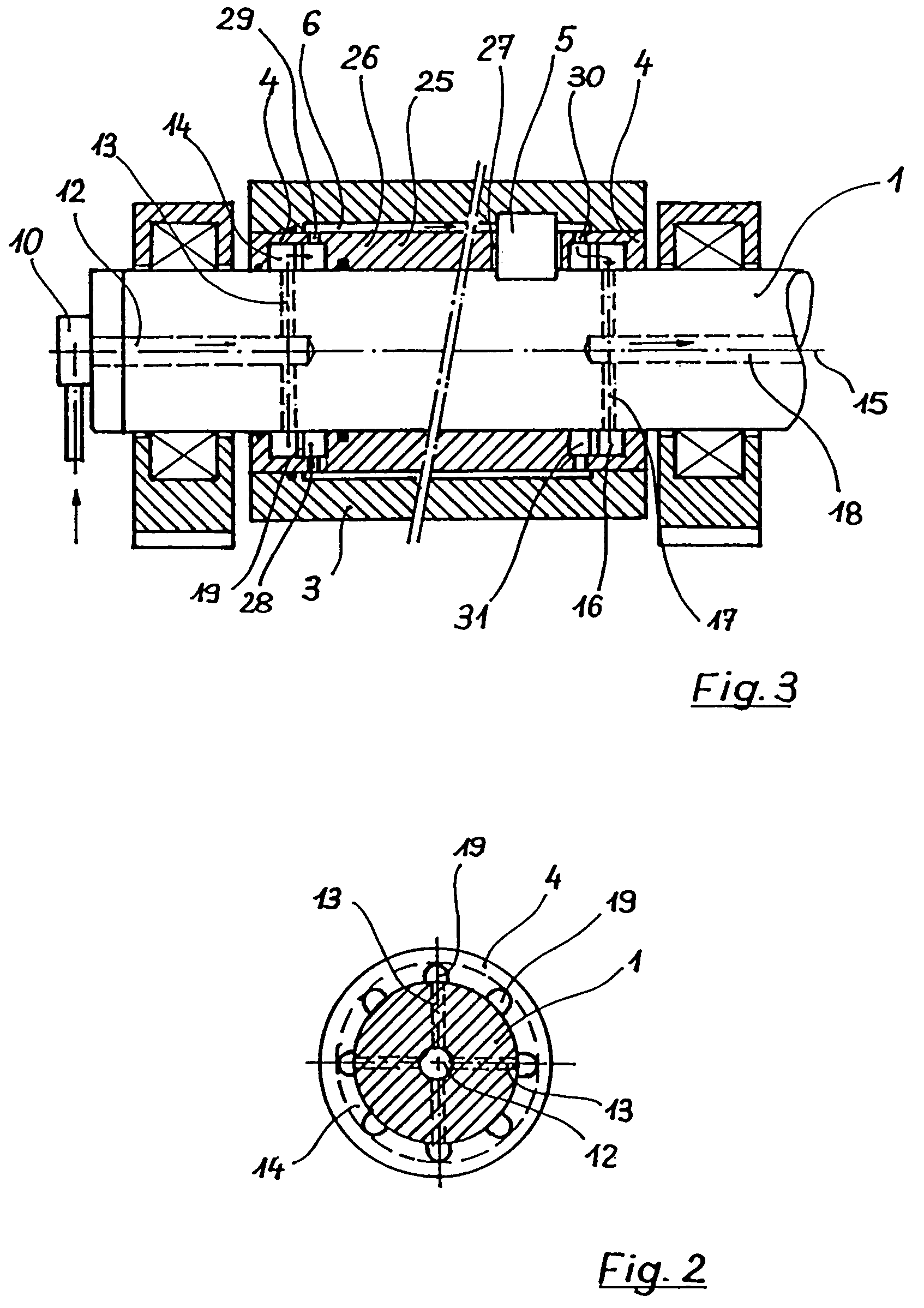
[0028]The strand-guiding roll illustrated in FIG. 1 comprises a central shaft 1, which is supported rotatably in four bearings 2. The bearings and the bearing housings which support them are in turn supported in a strand-guiding stand (not shown) of a continuous casting installation.

[0029]The bearings used are usually rolling-contact bearings. The central shaft 1 is assigned three roll shells 3, each of the three roll shells being supported on the shaft 1 by way of, in each case, two support rings 4. The bearings 2 are located outside the longitudinal extent of the adjacent roll shells 3. A rotation-preventing means 5 rotationally fixes the position of each roll shell 3 with respect to the shaft 1. An annular space 6, which forms a coolant conduit, is provided between the support rings 4 of a roll shell 3, the inner lateral surface of the roll shell and the outer lateral surface of the shaft 1. Strand-guiding rolls of the type according to the invention have at least two, and usuall...


PUM

PropertyMeasurementUnit
temperatureaaaaaaaaaa
thermal stressesaaaaaaaaaa
ferrostatic forcesaaaaaaaaaa

Abstract

A strand-guiding roll for supporting and guiding cast metal strands in a continuous casting installation, having a central rotatable shaft and having at least one roll shell supported fixed against rotation on this shaft. To enable the strand-guiding roll to cope with the mechanical and thermal stresses, the roll shell is supported by support rings or by a support-ring sleeve on the shaft. An annular space, which is axially delimited by the support rings for the shell, is formed between the shaft and the roll shell. The annular space is a coolant conduit.

Description

CROSS REFERENCE TO RELATED APPLICATION[0001]The present application is a 35 U.S.C. 371 national phase conversion of PCT / EP2004 / 003770, filed 8 Apr. 2004, which claims priority of German Application No. A 615 / 2003, filed 23 Apr. 2003. The PCT International Application was published in the German language.BACKGROUND OF THE INVENTION[0002]The invention relates to a strand-guiding roll for supporting and guiding cast metal strands in a continuous casting installation, having a central rotatable shaft and having at least one roll shell supported fixed against rotation on this shaft.[0003]Strand-guiding rolls are used in continuous casting installations to support and guide continuously cast metal strands after they emerge from a mold in a strand-guiding stand. They are exposed to high thermal stresses, since the cast metal strands leave the mold at a temperature of over 1000° C. if they are steel strands for example. In the case of relatively thick strands, there is still a pronounced li...

Claims


Application Information

Patent Timeline
17 Nov 2009
Publication
US7617862B2
IPC
B22D11/124; B22D11/128
CPC
B22D11/1287; F16C13/02; B22D11/124; B21B27/08
Inventors
GUTTENBRUNNER, JOSEF; STARRERMAIR, THOMAS