Controlling flow from multi-chamber containers

a multi-chamber, container technology, applied in the direction of pliable tubular containers, liquid handling, instruments, etc., can solve the problems of complex construction and difficult adjustment of the ratio of dispensing substances, and achieve the effect of reducing the effort of dispense, reducing the air bubbles in the product, and efficient and effective control of product flow

Inactive Publication Date: 2009-11-17
COLGATE PALMOLIVE CO
View PDF27 Cites 17 Cited by
  • Summary
  • Abstract
  • Description
  • Claims
  • Application Information

AI Technical Summary

Benefits of technology

[0006]The flow of product from each chamber of a multi-chamber tube can be affected by putting a flow control unit in one or more of the channels in the nozzle. The flow control unit, preferably is a constriction, and preferably is placed at an intermediate point in the channel, that is, at a point between the channel inlet and the channel exit. It can be placed on an exterior channel wall, an inner divider wall of the channels or on both walls. When on the exterior wall a viscous product being extruded from the tube will tend to have the separate strands come together at the dispensing nozzle exit. When on the interior divider wall the opposite effect of the strands diverging can occur. However, the constriction can be fully or partially on an inner wall, outer wall, or both walls. Usually the flow control unit only will be in one channel since this will efficiently and effectively control the flow of product. However it can be in both channels.
[0007]A constriction in a channel also will limit the suckback of a product back down the channel and into the tube shoulder and body. By limiting suckback the product from each chamber is maintained in a “dispensing ready” state, reducing effort to dispense the product and reducing air bubbles in the product.

Problems solved by technology

A problem that can arise in the dispensing of multi-component formulations from multi-chamber containers and how to get the desired amount to flow from each chamber, This can be equal amounts from each chamber, or differing amounts depending on the product and the components.
This may can be effective in some instances but is of a complex construction and difficult to adjust for dispensing the substance in varying ratios.

Method used


Image

  • Controlling flow from multi-chamber containers
  • Controlling flow from multi-chamber containers
  • Controlling flow from multi-chamber containers

Examples


Embodiment Construction

[0025]The invention will be described in more detail in its preferred embodiments with reference to the drawings. It is understood that the inventive concept is susceptible to additional embodiments, all of which are considered to be encompassed by the present invention.

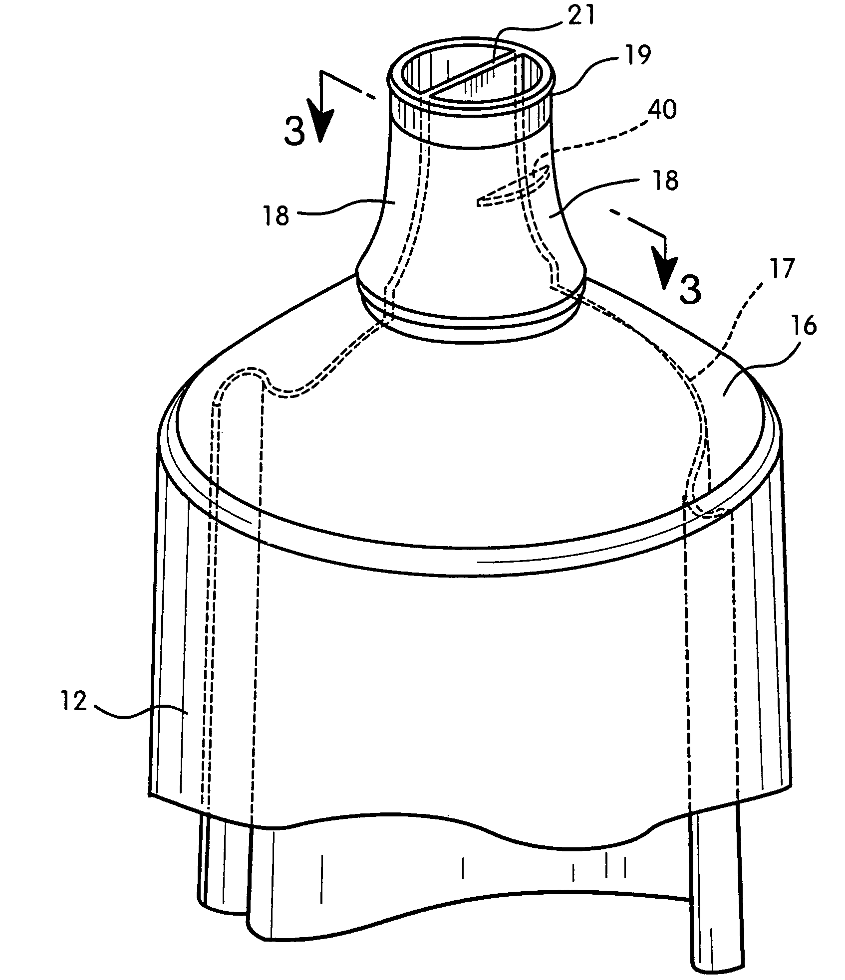
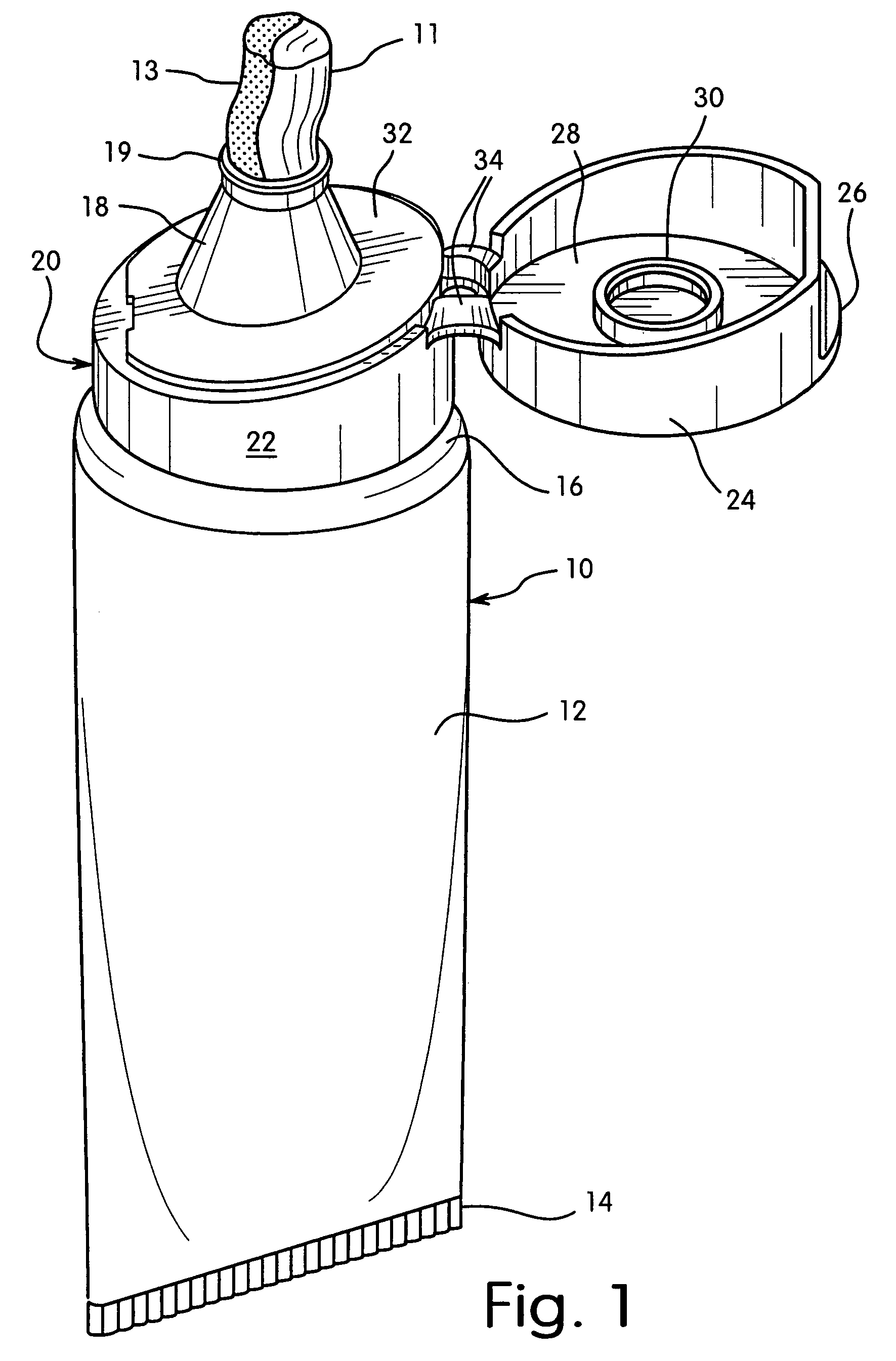
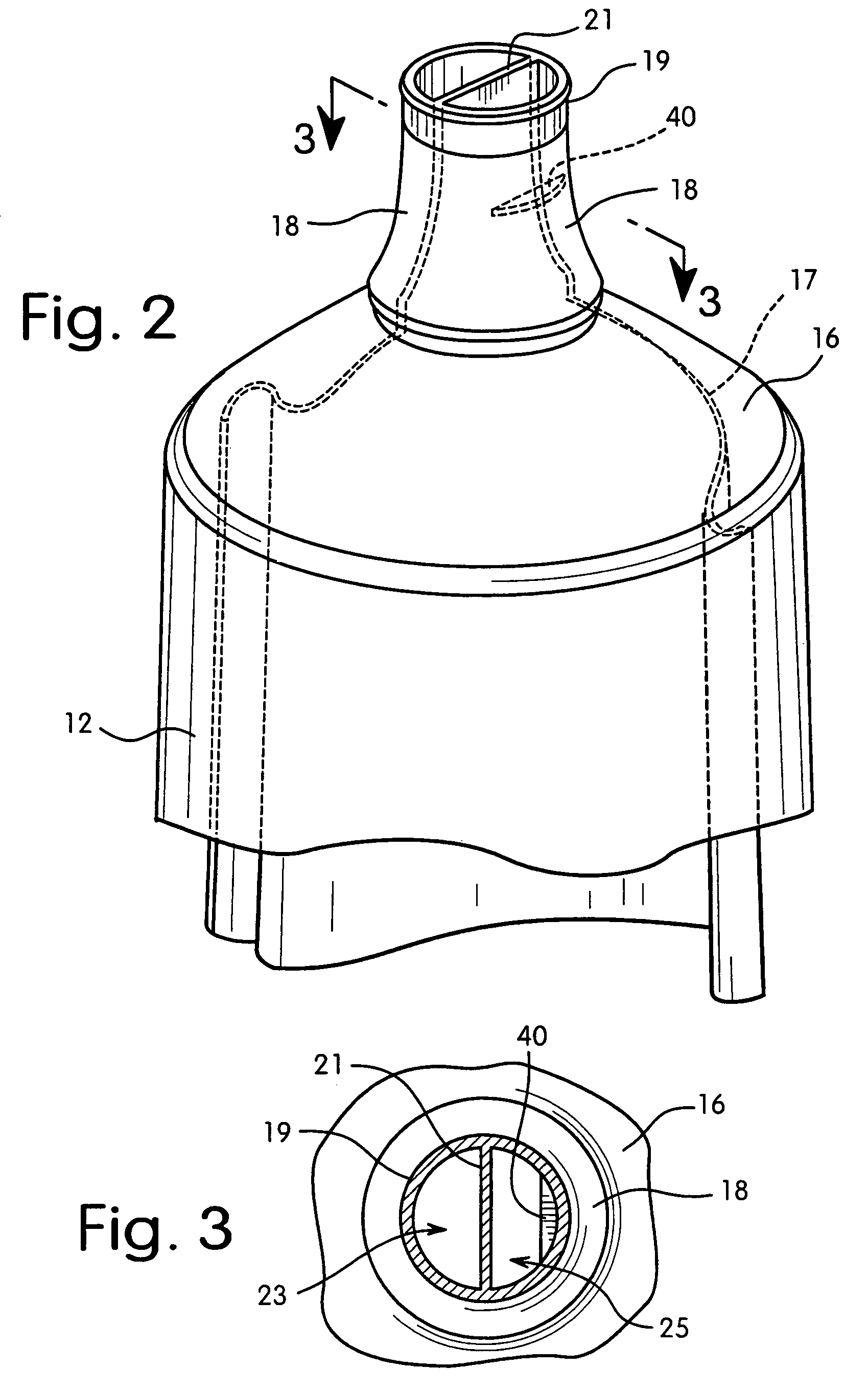
[0026]FIG. 1 is a perspective view of the multi-chamber container that utilizes a flow control device. This is shown as a dual chamber tube 10. The dual chamber tube is comprised of a tube body 12 with a crimp seal 14 at a lower end and a shoulder 16 at an upper end. The shoulder terminates in nozzle 18 which has an exit opening 19. There is shown in this view a dual component strand 11, 13 exiting the nozzle 18 of the dual chamber tube. Mounted on shoulder 16 is closure 20. This closure is comprised of a base portion 22 and a lid portion 24. The base portion has a deck 32 with a peripheral skirt 22. The nozzle 18 of the tube 10 extends upward through the deck 32. The lid 24 is attached to the deck by hinges 34. The ...


PUM


Abstract

The dispensing of substances from multi-chamber containers, such as tubes, can be controlled by the placement of a flow modifying unit in the dispensing nozzle of the container. The dispensing nozzle will have a plurality of channels, usually one for each chamber. The flow controlling unit is a constriction at an intermediate point, a point between the channel inlet and exit, in at least one of the channels. This constriction is sized to adjust flow so that the viscous substance from each chamber is dispensed at a set flow rate and in a set ratio, one to the other. The constriction is formed at the time that the nozzle is formed. In the compression molding process a mold pin is used, the mold pin meeting a mold base at an intermediate point in at least one channel. The mold pin and or mold base has a recess that is the size and shape of the flow modifying constriction. Plastic is injected into the mold and the flow modifying unit is formed at the same time as the nozzle.

Description

[0001]This invention relates to the control of flow of viscous substances from multi-chamber containers. Further this invention relates to a method to form a flow modifying unit in a dispensing nozzle as the nozzle is being formed.BACKGROUND OF THE INVENTION[0002]Multi-chamber containers are used for a number of products. The primary use is where a product is comprised of two or more incompatible components. These components must be kept separate until the time of use. At that time they can be mixed and used. The incompatibility can be the result of a fast or slow reaction between components. As an example oxidants and reducing agents must be kept separated. Likewise acids and bases must be kept separated. Consumer products where components must be kept separated include hair dye and bleaching products and some dentifrice such as high fluoride formulations, densitizing formulations, baking soda / peroxide formulations and peroxide tooth whitening formulations. A problem that can arise...

Claims


Application Information

Patent Timeline
Patent Type & Authority Patents(United States)
IPC IPC(8): B65D35/24
CPCB65D35/242
Inventor NORRIS, JOSEPH T.WALSH, SCOTT M.MILLER, CHRISTOPHER
Owner COLGATE PALMOLIVE CO
Why Eureka
Try Eureka