Battery cooling control system

a battery and control system technology, applied in battery/fuel cell control arrangement, electrochemical generators, etc., can solve the problems of excessive battery temperature rise, deterioration of battery performance and charge efficiency, adversely affecting not only the electric powered vehicle, etc., to prolong the life of the battery, reduce the effect of battery temperature ris

Active Publication Date: 2020-03-05
HONDA MOTOR CO LTD
View PDF0 Cites 3 Cited by
  • Summary
  • Abstract
  • Description
  • Claims
  • Application Information

AI Technical Summary

Benefits of technology

[0028]According to the present invention, even with a minimum system configuration, it is possible to efficiently and effectively control the cooling of the battery and restraining the temperature of the battery from rising excessively during charging by optimizing operating conditions of the cooling system.
[0029]As a result, according to the present invention, compared to the related art, it is possible to extend the life span of the battery, and to attain a reduction in charge time.

Problems solved by technology

However, if a large capacity of the battery and the high charge speed are applied, accordingly, the temperature of the battery may rise excessively while the battery is charged from an external power supply, and the performance and the charge efficiency of the battery may deteriorate, which is a problem.
In addition, if the charge efficiency deteriorates and the charge time is extended due to an occurrence of deterioration in the performance of the battery, for example, waiting lines for charging around a charging facility in a service area or parking area on a highway may become congested, or a power shortage of the EV may occur due to a user stopping a charge operation in the middle of charging instead of waiting for a full charge of the battery, thereby adversely affecting not only the electric powered vehicle but also a social system in the viewpoint of the widespread use of electric powered vehicles.
If it is intended that all heat generated by the battery during charging is taken away, the system may become enlarged or complicated, consume, more power, or have a weight increase in order to secure the corresponding cooling performance, thereby causing an increase in total cost.
For this reason, a countermeasure to take away all the heat generated by the battery during charging is not realistic.

Method used


Image

  • Battery cooling control system
  • Battery cooling control system

Examples


Embodiment Construction

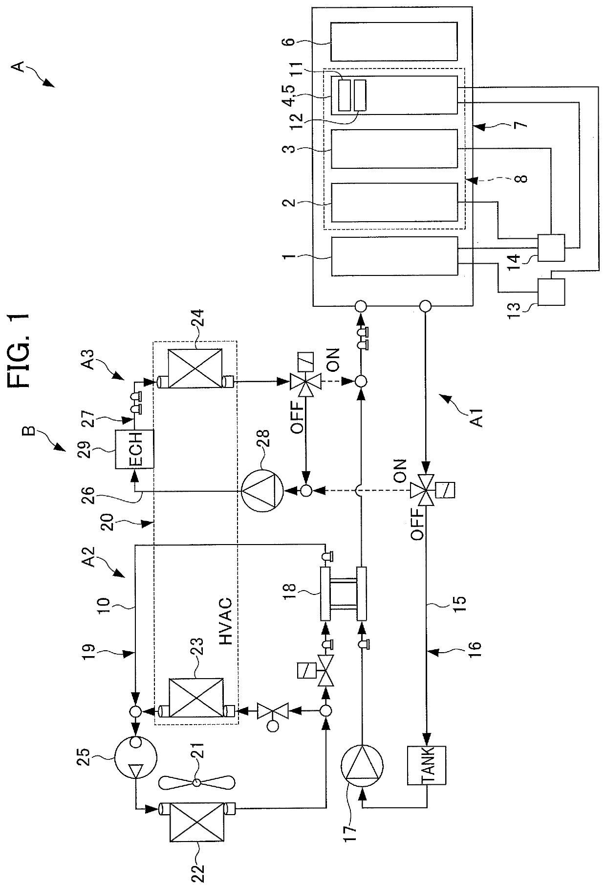
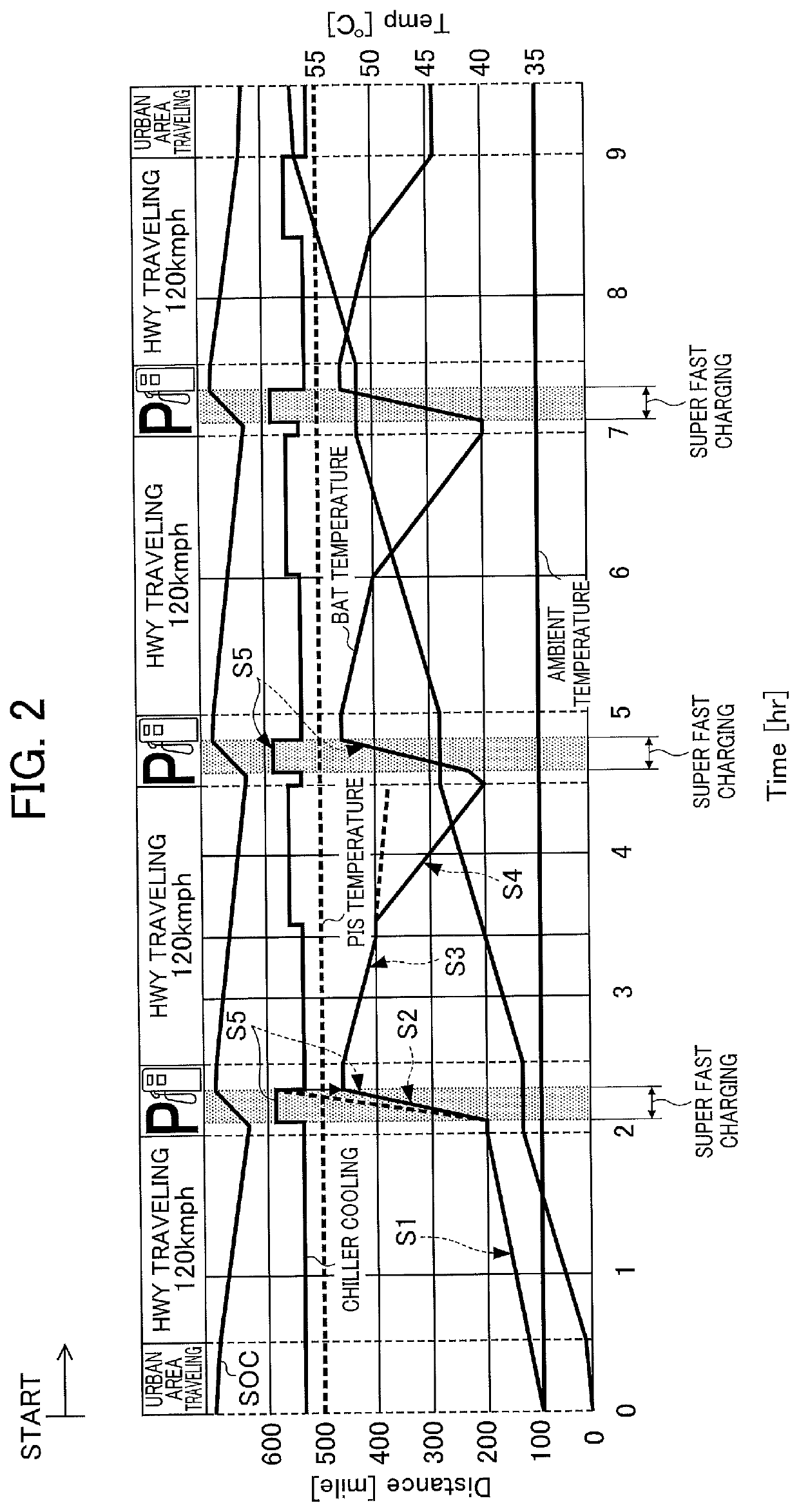
[0032]Hereinbelow, a battery cooling control system according to an embodiment of the present invention will be described with reference to FIGS. 1 and 2.

[0033]Herein, the present embodiment will be described based on the assumption that an electric powered vehicle is a hybrid vehicle and a drive battery is cooled using an air conditioning refrigerant of a cabin air conditioning cooling system of the electric powered vehicle. The electric powered vehicle according to the present invention may be certainly an electric vehicle or a fuel cell vehicle. In addition, the air conditioning refrigerant of the electric powered vehicle may not be necessarily used as a medium for cooling a battery.

[0034]Specifically, as illustrated in FIG. 1, the electric powered vehicle of the present embodiment includes an intelligent power unit (IPU) 7 formed of a drive battery 1 such as nickel-hydrogen cell or lithium-ion cell, an inverter (PDU) 2, a DC-DC converter 3, a motor electronic control unit (ECU: ...


PUM

PropertyMeasurementUnit
cooling capacityaaaaaaaaaa
temperatureaaaaaaaaaa
state of chargeaaaaaaaaaa

Abstract

There is provided a battery cooling control system capable of efficiently and effectively controlling the cooling of a battery. While an electric powered vehicle travels and/or stops, it is determined whether or not there is an indication of a battery being charged, and if it has been determined that there is the indication of charging being performed, it is determined whether or not there is a necessity for cooling the battery, and if it has been determined that there is the necessity for cooling the battery, the battery is cooled to a predetermined value during traveling. In addition, based on at least a state of charge of the battery and/or a driving range, it is determined whether or not there is an indication of charging being executed, and based on a real-time battery temperature, an increase in battery temperature caused by charging, and an upper limit value for a predetermined allowable battery temperature range, it is determined whether or not there is a necessity for cooling the battery.

Description

[0001]This application is based on and claims the benefit of priority from Japanese Patent Application No. 2018-165877, filed on 5 Sep. 2018, the content of which is incorporated herein by reference.BACKGROUND OF THE INVENTIONField of the Invention[0002]The present invention relates to a battery cooling control system.Related Art[0003]In the related art, an electric powered vehicle such as a fuel cell vehicle, an electric vehicle, or a hybrid vehicle includes, for example, a power control unit (PCU, power conversion device) including an inverter by which direct current power supplied from a drive battery (storage cell) is converted into 3-phase alternating current power; a drive motor (containing a drive motor-generator and the like) that is driven by the 3-phase alternating current power converted by the inverter of the PCU; and a power transmission mechanism that drives the electric powered vehicle to travel by transmitting a drive force of the drive motor to wheels.[0004]In such ...

Claims


Application Information

Patent Timeline
Patent Type & Authority Applications(United States)
IPC IPC(8): H01M10/633H01M10/613H01M10/615H01M10/625H01M10/655H01M10/6564H01M10/663H01M10/6572
CPCH01M10/655H01M10/633H01M10/613H01M10/625H01M10/615H01M10/663H01M10/6572H01M10/6564B60L58/26B60H1/00278B60H1/00385H01M10/63H01M2220/20H01M10/657B60L58/24Y02T10/70Y02T10/7072Y02T90/14Y02E60/10
Inventor OGAKI, TORUMATSUMOTO, MANABU
Owner HONDA MOTOR CO LTD
Why Eureka
Try Eureka