Ink tank and recording apparatus using ink tank

a technology of ink tank and recording apparatus, which is applied in the direction of mixing, printing, mixing, etc., can solve the problems of ink flow, inability to increase the swing range of the stirrer, and difficulty in maintaining the quality of dye ink for outdoor printed materials, and achieves efficient agitation of ink. , high quality

Inactive Publication Date: 2009-11-17
CANON KK
View PDF9 Cites 4 Cited by
  • Summary
  • Abstract
  • Description
  • Claims
  • Application Information

AI Technical Summary

Benefits of technology

[0016]The present invention is directed to an ink tank capable of efficiently agitating ink in an ink tank and a recording apparatus capable of recording a high quality image using ink of uniform thickness.
[0017]According to an aspect of the present invention, an ink tank includes a housing, an ink container disposed in the housing, and an ink supply port. The ink container is adapted to contain ink. The ink container includes a stirrer configured to agitate the ink and a supporting portion for supporting the stirrer. An inner wall of the housing defines an inner surface of the ink container. An ink supply port facilitates supplying the ink contained in the ink container to outside the ink tank. In the ink tank, the supporting portion is provided at least one of a position on the inner wall and a position in the vicinity of the inner wall so that the stirrer is capable of moving close to and apart from the inner wall, the stirrer has a supported end supported by the supporting portion and a moving end swingable about the supported end, and an area of a segment of the stirrer adjacent to the supported end is smaller than an area of a segment of the stirrer adjacent to the moving end.
[0019]According to the present invention, the proximal end of a stirrer is pivotally supported by the housing of an ink tank in the vicinity of the inner wall of the ink tank. When the stirrer moves close to the inner wall, the stirrer is substantially parallel to the inner wall. Consequently, a strong ink flow can be generated. Furthermore, a space is formed in the stirrer in the vicinity of the proximal end of a stirrer. Thus, a strong ink flow is generated in the vicinity of the proximal end of a stirrer, and therefore, the ink can be more efficiently agitated.
[0020]As a result, for example, before the recording operation is started or during the recording operation, by reciprocally moving the carriage including the ink tank, the ink in the ink tank can be efficiently agitated. In addition, even after the recording apparatus with the ink tank mounted therein remains unused for a long time, the ink can be sufficiently agitated simply by moving the carriage reciprocally in a short time before the recording operation is started. Accordingly, the recording operation can be started immediately after the recording apparatus is powered on. Furthermore, when pigment-based ink is contained in the ink tank, the concentration of the pigments can be uniform, and therefore, a high-quality image can be recorded.

Problems solved by technology

However, it is difficult to maintain the quality of dye ink for outdoor printed materials (such as resistance to light and resistance to climate).
However, since the pigment is not dissoluble, but dispersible, it is inevitable that pigment particles settle out inside an ink tank.
First, in the ink tank described in Japanese Patent Laid-Open No. 2004-216761, the stirrer swings about substantially the center of the ink tank similarly in one direction and the opposite direction. Accordingly, in order to increase the agitating performance by increasing the swing range of the stirrer, the width of the ink tank needs to be increased in the carriage movement direction. However, since, in most cases, a plurality of ink tanks are mounted in the carriage along the carriage movement direction, the width of the ink tank is limited to a relatively small value. Thus, the swing range of the stirrer cannot be increased. Therefore, the ink flow caused by the swing of the stirrer is weak. To sufficiently agitate the ink, the agitating time needs to be increased by increasing the number of reciprocal movements of the carriage.
Therefore, this structure has the same disadvantage as that of the ink tank described in Japanese Patent Laid-Open No. 2004-216761.
Additionally, if the acceleration of the carriage is set to be high in order to cause large elastic deformation of the stirrer, the size and the manufacturing cost of a driving motor for driving the carriage increases.
In addition, the vibration of the recording apparatus may increase.
Furthermore, for the ink tank described in Japanese Patent Laid-Open No. 2005-066520 and having a stirrer freely movable on the bottom surface of the ink tank, since the stirrer is distant from the upper layer of ink in the ink tank, the performance of agitating the ink in the upper layer is not satisfactory.
Therefore, in the main scanning direction, which is a direction in which the stirrer is displaced, a large amount of displacement cannot be achieved.
Since the amount of displacement of the stirrer is small, a strong ink flow cannot be generated.
For this reason, the efficiency of agitating the ink is low and a long time is required for agitating the entire ink inside the ink tank.
For example, when the recording apparatus with an ink tank mounted to the carriage is not operated for a long time and pigment particles of the ink in the ink tank settle out, reciprocal movements of the carriage is required for a long time before the recording operation starts.
Thus, a long warm-up time is required before the recording operation becomes ready.
If the ink tank remains unused even for several days, the concentration distribution of ink that causes an adverse effect on the quality of a recording image may be generated.
In addition, during the agitating operation, recording operation cannot be carried out.

Method used


Image

  • Ink tank and recording apparatus using ink tank
  • Ink tank and recording apparatus using ink tank
  • Ink tank and recording apparatus using ink tank

Examples


first exemplary embodiment

[0036]Structure of Ink Tank

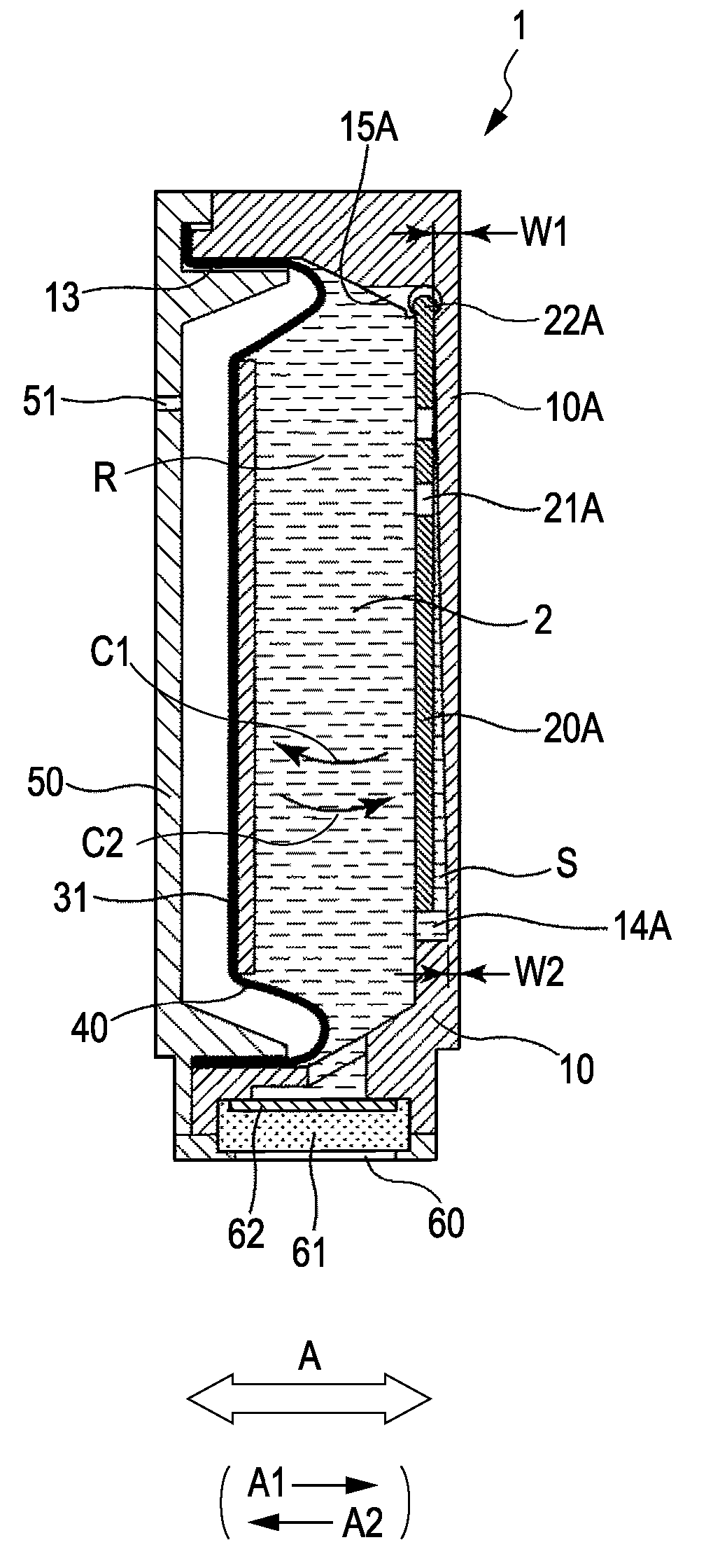
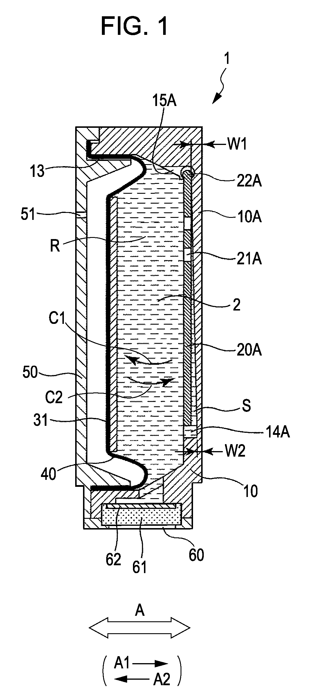
[0037]FIG. 1 is a cross-sectional view of an ink tank 1 according to a first embodiment of the present invention. FIG. 2 is an exploded perspective view of the ink tank 1. FIG. 1 corresponds to a cross-sectional view taken along line I-I of FIG. 2.

[0038]The ink tank 1 is a container in which an ink container R formed from a tank case 10 and a flexible member 40 is filled with ink 2. As shown in FIG. 1, the ink tank 1 is mounted to an inkjet recording apparatus with an ink supply port 60 facing downward. The ink supply port 60 is connected to an ink supply channel of an inkjet recording head, which will be described below. According to the present embodiment, the ink tank 1 can be removed from the recording head. However, the ink tank 1 may be irremovably integrated into the recording head.

[0039]As shown in FIG. 2, the ink tank 1 includes the tank case 10, stirrers 20A and 20B, a spring 30, a pressing plate 31, the flexible member 40, and a cover 50. The ta...

second exemplary embodiment

[0072]FIG. 10 is a cross-sectional view of an ink tank according to a second embodiment of the present invention.

[0073]According to the second embodiment, when, as shown in FIG. 10, the ink tank is disposed with an ink supply port 60 facing downwards, pivot shafts 22C and 22D of stirrers 20C and 20D are supported by supporting portions 15C and 15D so as to be swingable about a substantially vertical axis. Basically, the supporting portions 15C and 15D and the pivot shafts 22C and 22D are similar to the above-described supporting portions 15A and 15B and pivot shafts 22A and 22B, respectively. However, mounting positions thereof are different. A plurality of through-holes 21C and 21D are formed in the stirrers 20C and 20D at positions adjacent to the pivot shafts 22C and 22D, respectively. Like the first embodiment, the ink tank reciprocally moves in a main scanning direction indicated by arrow A together with a carriage 153. Thus, the inertia force causes stirrers 20C and 20D to swi...

third exemplary embodiment

[0074]FIG. 11 is a cross-sectional view of an ink tank 1 according to a third embodiment of the present invention.

[0075]In the above-described embodiments, the ink tank 1 has a structure in which a predetermined negative pressure is maintained in the ink container R using a negative pressure control mechanism including the flexible member 40 and the spring 30. According to the third embodiment, the ink tank 1 includes an outside-air intake mechanism for controlling the pressure in the ink container R to be a predetermined negative pressure. The outside-air intake mechanism draws the outside air into the ink container R so as to maintain the pressure in the ink container R to be a predetermined negative pressure with respect to the atmosphere. For example, the outside-air intake mechanism may have a structure in which a small gap is provided to the bottom surface of the ink tank 1 and the meniscus formed by the ink in the gap causes the pressure in the ink container R to be negative ...


PUM


Abstract

An ink tank includes a tank case and a stirrer. The proximal end of the stirrer is supported by the inner surface of the tank case in a pivotal manner. When the stirrer moves close to the inner surface of the ink tank, the stirrer is substantially parallel to the inner surface. The stirrer includes a through-hole in the vicinity of the proximal end thereof.

Description

BACKGROUND OF THE INVENTION[0001]1. Field of the Invention[0002]The present invention relates to an ink tank and a recording apparatus using the ink tank.[0003]2. Description of the Related Art[0004]Examples of recording apparatuses using ink contained in an ink tank include inkjet recording apparatuses having an inkjet recording head capable of ejecting ink. Such inkjet recording apparatuses include a serial-scanning-type inkjet recording apparatus that records an image on a recording medium by moving a carriage including an inkjet recording head and an ink tank in a main scanning direction.[0005]The serial-scanning-type inkjet recording apparatus includes a carriage having an inkjet recording head and an ink tank for supplying ink to the inkjet recording head. To perform recording, the inkjet recording apparatus moves the carriage relative to a recording medium and ejects ink droplets from a small ejection port. The ejected ink droplets are deposited on the recording medium so tha...

Claims


Application Information

Patent Timeline
Patent Type & Authority Patents(United States)
IPC IPC(8): B41J2/175
CPCB01F11/0022B41J2/17556B41J2/17513B01F11/04B01F31/24B01F31/42
Inventor INOUE, RYOJIKOTAKI, YASUOOHASHI, TETSUYAKAWAMURA, SHOGOOGURA, HIDEKI
Owner CANON KK
Why Eureka
Try Eureka