Anisotropic conductive connector and anisotropic conductive connector connection structure

a technology of anisotropic conductive connectors and conductive connectors, which is applied in the direction of connection contact material, elastomeric connecting elements, coupling device connections, etc., can solve the problems of noise generation, inability to press-hold a small sponge with a conductive cloth between the casing and the board, and the difference in potential generated between one metal portion and another metal portion, etc., to achieve the effect of facilitating the mounting operation

Inactive Publication Date: 2009-11-17
POLYMATECH CO LTD
View PDF4 Cites 17 Cited by
  • Summary
  • Abstract
  • Description
  • Claims
  • Application Information

AI Technical Summary

Benefits of technology

[0010]The present invention has been made in view of the above-mentioned problems in the prior art. It is accordingly an object of the present invention to provide a grounding technology which provides the requisite conduction characteristic for ground connection even with a small grounding area. Another object of the present invention is to provide a grounding technology which facilitates the mounting operation.

Problems solved by technology

When a mobile electronic apparatus has metal portions, there is a fear of a difference in potential being generated between one metal portion and the other metal portion and noise being generated within the electronic apparatus, and hence it is necessary to effect grounding connection between the metal portion and the other metal portion.
It should be noted, however, that it is rather difficult to press-hold a small sponge with conductive cloth between the casing and the board at a predetermined position.
Further, due to its rather poor dimensional precision, the size of the sponge sometimes exceeds the accommodation space acceptable for the mobile electronic apparatus, which is required to be as small as possible.
Further, it only allows production in a simple configuration such as a rectangular prism, and hence it cannot be applied to ground connection which involves a complicated configuration.
However, the small grounding spring, which is formed of a metal piece, is subject to deformation, and when it is excessively deformed, it cannot be restored to the former shape, thus failing to perform ground connecting function.
Further, the grounding spring is held in point contact with the ground connecting portion, and hence it is not always to be expected to exhibit a sufficient conduction characteristic.
It should be noted, however, that it is rather difficult to press-hold the small columnar conductive silicone rubber member between the casing and the board at a predetermined position.
However, when the amount of conductive filler is larger, the silicone rubber becomes rather hard, fragile, and subject to chipping.

Method used


Image

  • Anisotropic conductive connector and anisotropic conductive connector connection structure
  • Anisotropic conductive connector and anisotropic conductive connector connection structure
  • Anisotropic conductive connector and anisotropic conductive connector connection structure

Examples


first embodiment (

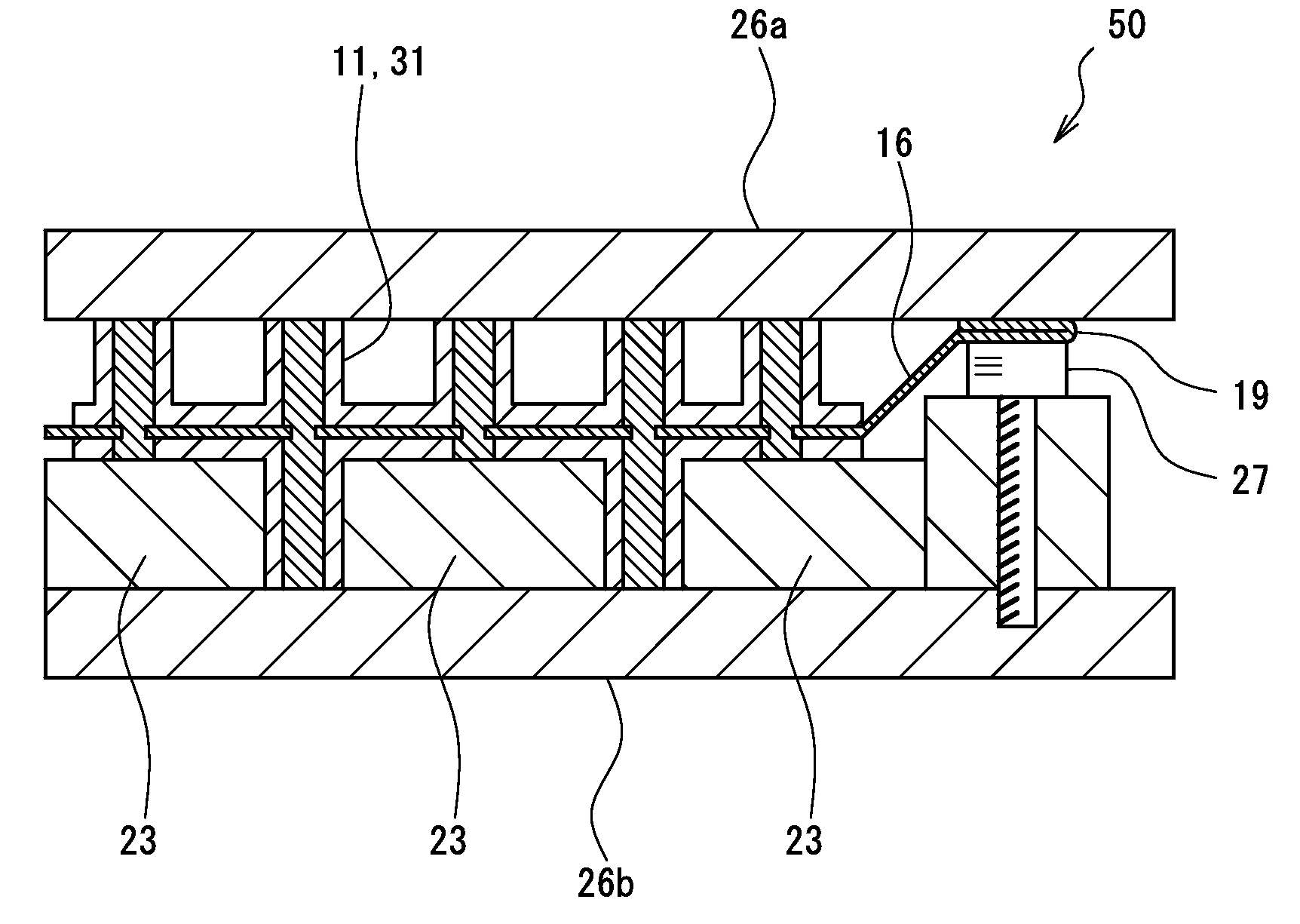
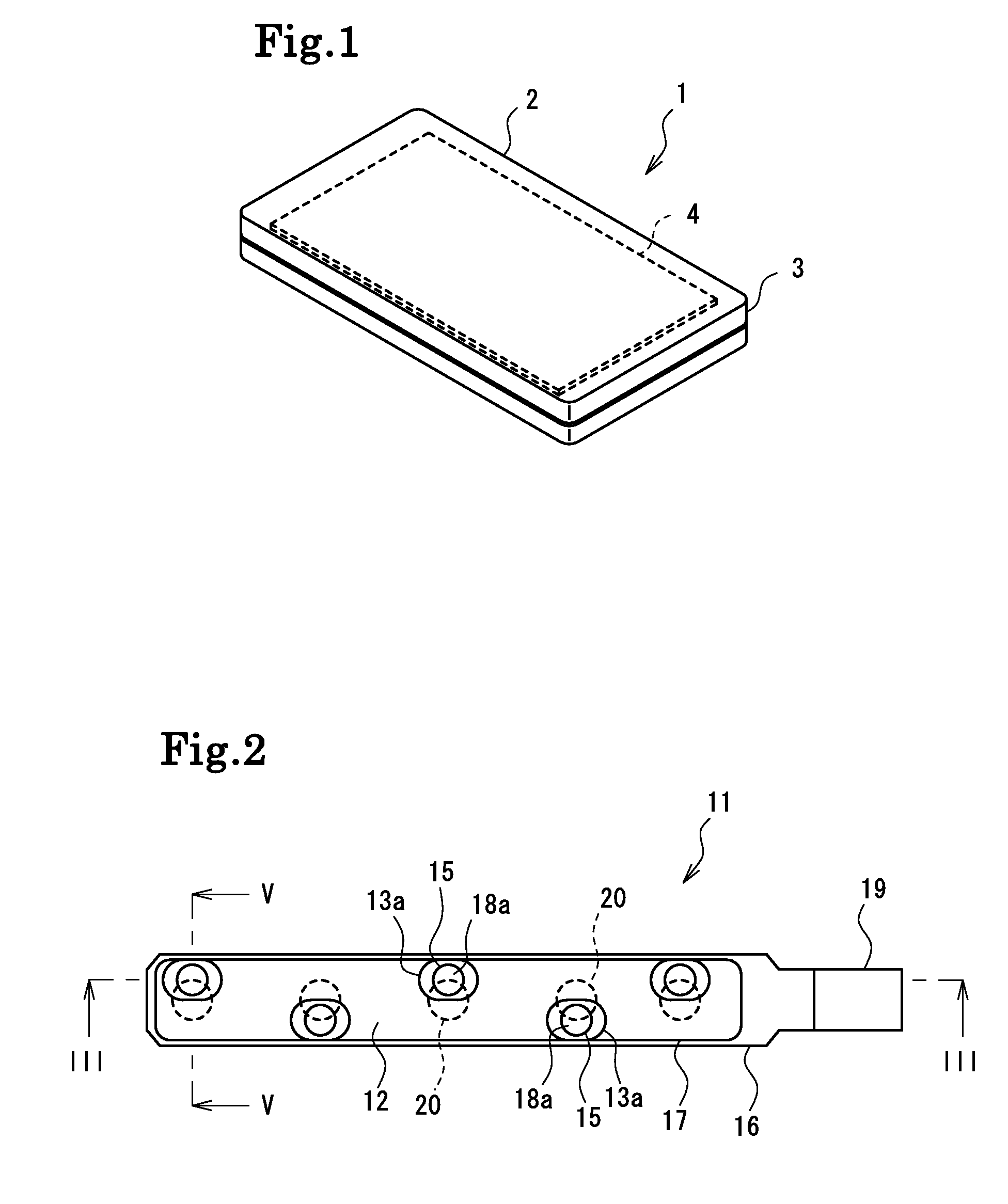
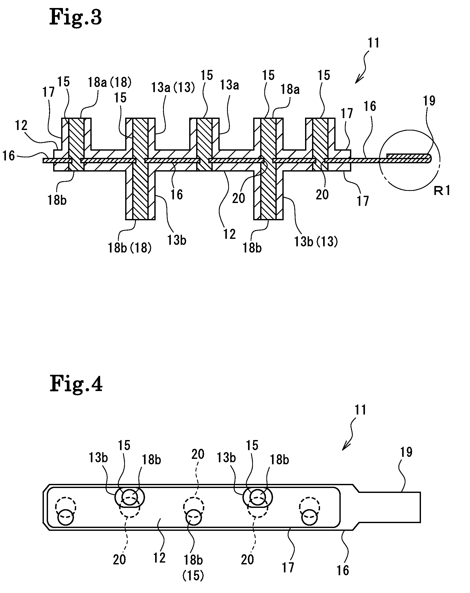
[0042FIGS. 2 through 5): FIG. 2 is a plan view of an anisotropic conductive connector 11 according to this embodiment, FIGS. 3 and 5 are sectional views of the same, and FIG. 4 is a bottom view of the same. In terms of structure, the anisotropic conductive connector 11 has a plurality of protrusions 13 (upper side protrusions 13a and lower side protrusions 13b) vertically protruding from a base body portion 12 expanding in a plate-like fashion in the thickness direction thereof. In terms of function, the anisotropic conductive connector 11 has conducting paths 15 for effecting conduction between one side (e.g., the upper side) and the other side (e.g., the lower side) of the anisotropic conductive connector 11, a conduction sheet 16 having a metal portion 16a effecting conduction between the conducting paths 15, and an insulating portion 17 covering the conducting paths 15 and the conduction sheet 16 and preventing exposure of the conductive portions to insulate them from the exteri...

second embodiment (

[0061FIGS. 10 through 13): FIG. 10 is a plan view of an anisotropic conductive connector 31 according to the second embodiment of the present invention, FIGS. 11 and 13 are sectional views thereof, and FIG. 12 is a bottom view thereof. The anisotropic conductive connector 31 differs from the anisotropic conductive connector 11 of the above-mentioned embodiment in the size of through-holes 40 provided in a conduction sheet 36 and the positions where protrusions 33 (upper protrusions 33a and lower protrusions 33b) are provided.

[0062]As shown in FIGS. 10 and 12, in the anisotropic conductive connector 31, the through-holes 40 are formed in the conduction sheet 36 at positions in the center line of the anisotropic conductive connector 31. Further, the upper protrusions 33a and the lower protrusions 33b are also formed at positions in the center line of the anisotropic conductive connector 31. The portion where each conducting path 35 and the conduction sheet 36 cross each other is descr...


PUM


Abstract

An anisotropic conductive connector includes: a plurality of conducting paths to be brought into contact with a first object of connection provided in an electronic apparatus and with a second object of connection separate from the first object of connection to effect conductive connection between the objects of connection; and a metal portion to be brought into contact with the conducting paths to effect conductive connection between the plurality of conducting paths.

Description

[0001]This application claims the priority benefit under 35 U.S.C. § 119 of Japanese Patent Application No. 2007-214597 filed on Aug. 21, 2007, which is hereby incorporated in its entirety by reference.BACKGROUND OF THE INVENTION[0002]1. Field of the Invention[0003]The present invention relates to a technology for effecting grounding connection between an object of connection continuous with a metal portion of an electronic component or the like contained in an electronic apparatus such as a mobile phone, a personal digital assistant, a mobile music player, or a vehicle-mounted apparatus, and an object of connection continuous with another metal portion.[0004]2. Description of the Related Art[0005]Some mobile electronic apparatuses such as a mobile phone and a personal digital assistant use an electronic component and a member having metal portions. When a mobile electronic apparatus has metal portions, there is a fear of a difference in potential being generated between one metal p...

Claims


Application Information

Patent Timeline
Patent Type & Authority Patents(United States)
IPC IPC(8): H01R4/58
CPCH01R4/66H01R13/2414H01R12/7082H05K1/0215H01R43/007H01R11/01
Inventor KONNO, HIDEAKINAKAGAWA, TAKASHI
Owner POLYMATECH CO LTD
Why Eureka
Try Eureka