Endoscopic suturing system

Active Publication Date: 2009-11-17
OLYMPUS CORP +1
View PDF11 Cites 43 Cited by
  • Summary
  • Abstract
  • Description
  • Claims
  • Application Information

AI Technical Summary

Benefits of technology

[0005]The present invention has been made in view of the above described circumstance. It is an object of the present invention to provide

Problems solved by technology

However, the posts and devises interfere with each other, whereby an angle that can be formed between the devises is restricted to an angle of about 90 degr

Method used


Image

  • Endoscopic suturing system
  • Endoscopic suturing system
  • Endoscopic suturing system

Examples


first embodiment

[0147]FIG. 1 to FIG. 29 show an endoscopic suturing system according to a first embodiment of the present invention. In the respective systems described hereinafter, although the endoscopic suturing system is used, a gripping forceps, a scissors forceps, a hot biopsy forceps, or a rotational clipping device may be used instead of the suturing system.

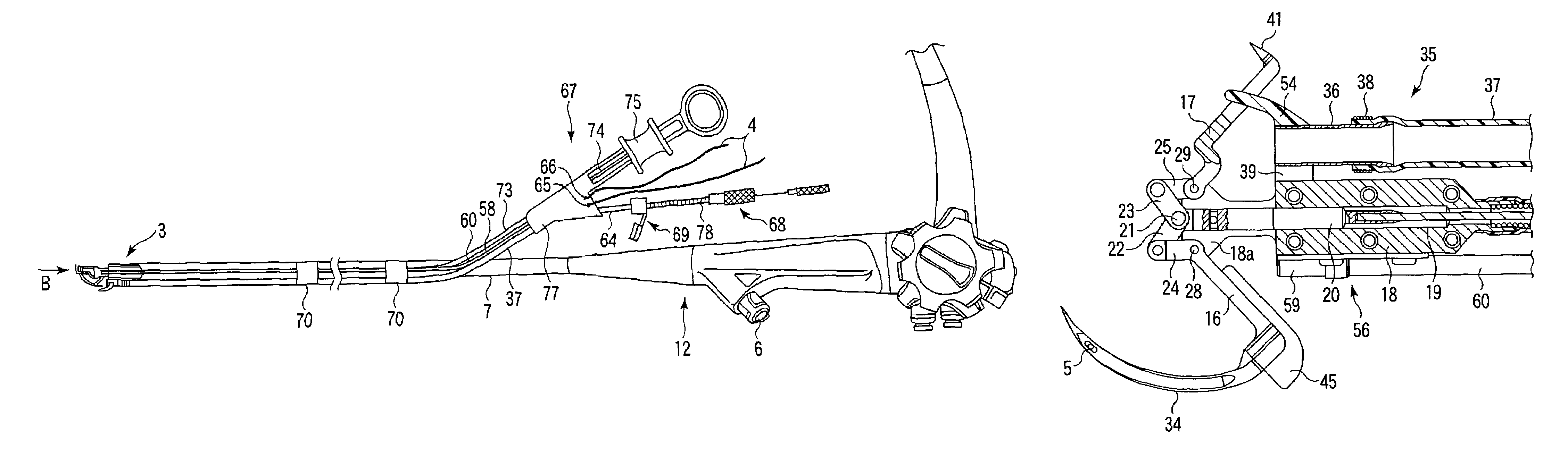
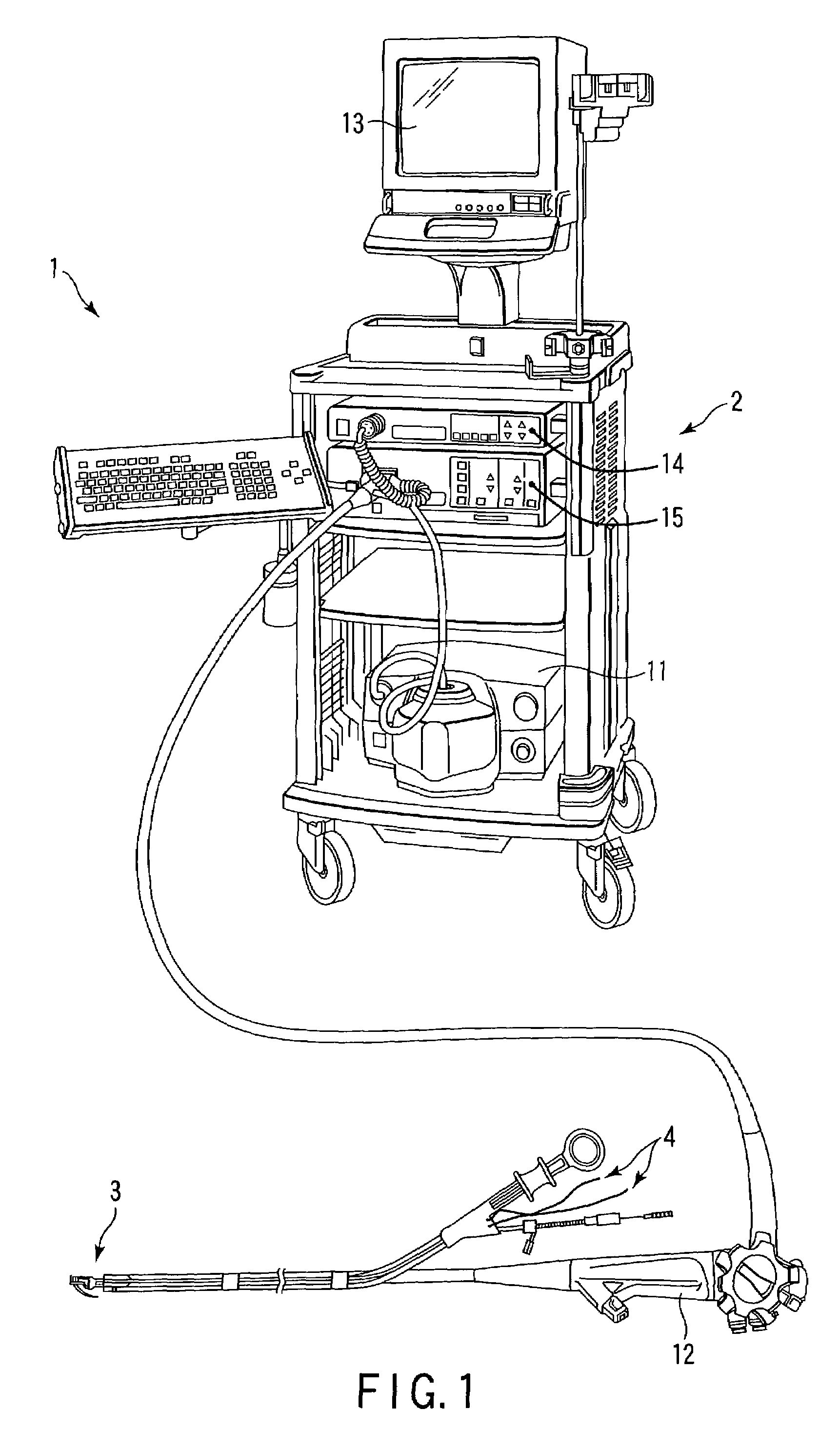
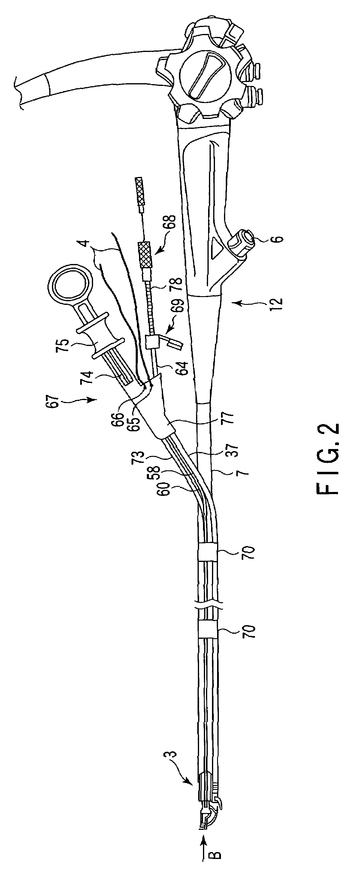
[0148]As shown in FIG. 1, an endoscopic suturing system 1 according to the present embodiment comprises an endoscope system 2, a suturing device 3, and a suture thread 4. This suture thread 4 is preferably formed like a monofilament line or stranded wire by using a material such as nylon, polyester, silk, fluoroplastic or bioabsorbable resin. The endoscope system 2 comprises an endoscope 12, an image processing device 14, a light source device 15, an observation monitor 13, and a suction device 11 as in a generally used videoscope system. The endoscope 12 is connected to the light source device 15 via a universal code. Then, an image sig...

second embodiment

[0188]FIG. 30 to FIG. 35 each show an endoscopic suturing system according to a second embodiment of the present invention. A variety of endoscopes described hereinafter are basically similar to those according to the above described embodiment. Like elements are designated by like reference numerals. A detailed description thereof is omitted here.

[0189]As shown in FIG. 30 and FIG. 31, a system according to the present embodiment comprises a protect member 100 mounted at a distal end portion of the insert portion 7 of the endoscope 12, the protect member 100 covering the distal end portion of the suturing device 3. This protect member 100 comprises: a cylindrical fixing portion 104, for example, that can be removably fixed at a distal end of the insert portion 7; and a movable portion 103 slidably mounted on the outer periphery of this fixing portion 104. This movable portion 103 is preferably made of a transparent resin, e.g., polycarbonate, norbornene resin, cycloolefin-based resi...

third embodiment

[0200]FIG. 36 shows a protect member 122 used for an endoscopic suturing system according to a third embodiment of the present invention.

[0201]The protect member 122 according to the present embodiment comprises: a fixing portion 124 fixed to a distal end portion of an insert portion 7; and a movable portion 123 that can slide on this fixing portion 124. An externally sealed annular space 128 is formed between these fixing portion and movable portion. A base 125 communicating with the annular space 128 is mounted at the outer periphery of the movable portion 123, a fluid 127 can be poured into or discharged from the annular space 128. This fluid 27 may be liquid or gas.

[0202]In the present embodiment, at the protect member 122, for example, when the suitable fluid 127 such as physiological saline, water, or air is filled in a fluid pouring device (not shown) such as syringe, and this fluid is poured into the annular space 128, the movable portion 123 slides to the right side on pape...


PUM


Abstract

An endoscopic treatment device is used with an endoscope. This treatment device includes a transmission member with a flexible structure having a distal end portion to be inserted into a body and can be operated outside the body, a push rod coupled to the distal end portion, and first and second connecting members rotatably coupled to the push rod. The treatment device further includes first and second arm members rotatably coupled to the distal end portion of the connecting member, a holding member rotatably holding the respective arm at a predetermined interval therebetween, and first and second actuating members integrally formed with the arm members and can open/close when the transmission member actuates the first and second connecting members and the first and second arm members through the push rod. This device also includes a needle mounted on at least one of the first and second actuating members.

Description

CROSS-REFERENCE TO RELATED APPLICATIONS[0001]This application claims the benefit of U.S. Provisional Application No. 60 / 352,728, filed Jan. 30, 2002; and No. 60 / 430,259, filed Dec. 2, 2002.BACKGROUND OF THE INVENTION[0002]The present invention relates to a treatment device which can be inserted into a body together with an endoscope. U.S. Pat. No. 5,171,258 (Symbiosis Co., Ltd.) discloses a medical instrument that is applicable to a surgical operation using a laparoscope. This medical instrument comprises a pair of posts for supporting a pair of devises in order to produce a large force required to grip a thick tissue. However, the posts and devises interfere with each other, whereby an angle that can be formed between the devises is restricted to an angle of about 90 degrees.[0003]On the other hand, where the inside of a body is sutured by using an endoscope, it is required to puncture a needle through a tissue. Therefore, a treatment device is required to be a small size, neverthe...

Claims


Application Information

Patent Timeline
IPC IPC(8): A61B17/10A61B17/06A61B17/04A61B17/064
CPCA61B17/0467A61B17/0487A61B17/0469A61B2017/06057A61B17/0485A61B17/0493A61B17/06066A61B17/0643A61B2017/0445A61B2017/045A61B2017/0458A61B2017/0464A61B2017/0472A61B2017/0474A61B2017/0475A61B2017/0477A61B2017/0488A61B2017/06019A61B2017/06028A61B2017/06042
Inventor YAMAMOTO, TETSUYACHUNG, SYDNEY SHEUNG CHEEKAWASHIMA, KOICHI
Owner OLYMPUS CORP
Why Eureka
Try Eureka