Bone staple and methods for correcting spine disorders

a spine disorder and bone staple technology, applied can solve the problems of not widely and intensively imposed use of this device, not widely and widely imposed in the medical field, and not working satisfactorily

Inactive Publication Date: 2009-11-17
GROISO JORGE ABEL
View PDF5 Cites 76 Cited by
  • Summary
  • Abstract
  • Description
  • Claims
  • Application Information

AI Technical Summary

Benefits of technology

[0022]a shape memory material body comprising a cross bar and at least two legs extending from the cross bar and normally diverging from each other, wherein the legs define spring legs tending to expand apart from each other when subject to a compression force, whereby when the staple is introduced into a bone with each leg at each side of the epiphyseal plate under a compression force bringing the legs to be closer than in a normal position the legs exert a expansion force for lengthening the epiphyseal plate while the cross bar keeps a normal length thereof forming a tether for a periphery of the epiphyseal plate, thus causing the epiphyseal plate to growth around a focus.
[0046]It is a further object of the present invention to provide a method and staple for correcting an abnormally curved spinal column having a concave side and a convex side, the method comprising providing a staple having a central portion and a pair of legs with a first memorized shape and a second deformed shape and implanting the staple, in the second shape, at the convex side of the spinal column in a manner that the legs extend close to the concave side, such that the legs exert a distraction force at the concave side of the spinal column.

Problems solved by technology

Since the use of external fixators for the above described mechanical suppressing techniques has shown to be expensive as well as traumatic and cumbersome for the patient, and the fixator leaves unsightly scars, the use of this device has not widely and intensively imposed.
It would be desirable to use staples for these techniques, however, the staples are affected by several disadvantages and drawbacks that caused them to be not widely imposed in the medical field.
Another drawback the physicians have found with the use of staples is that the same do not work satisfactorily because the bone growth is not restarted afterwards, thus producing the appearance of opposite deformity due to the constant growth of the cartilage of the side that was not operated upon.
As the staple is hammered up to abutting the external surface of the bone, the reinforcements, as well as the flat bridge or cross bar enter into contact with the growth plate and damage the perochondrium and the perichondrial vessels, this being the cause of the undesired epiphysial arrest.
However, when the deformation has been corrected and the temporary staple must be removed from the bone, the anchorage of the legs into the growing bone mass, desired at the time the stable must be retained into the bone, is a bar or obstacle at the time the staple must be removed.
While no compression is made the distraction is obtained by employing complex, cumbersome and dangerous systems.
While this system is simple, it consists of at least three parts which is a drawback when it is working in a most sensitive area like the spinal column and, particularly when as smallest as possible tools are desired to be employed in the intervention.
In addition, the use of fasteners, such as screws, is less and less preferred for the patient security.
Another drawback of Bauer's system, which is not less important, is that the implant is attachable to the concave side of the spinal column with the undesired result that not only the concave side is distracted but also the convex side.
In deed the growth of the vertebrae end plates at the convex side are inconveniently promoted with the final result of an abnormally elongated spine.

Method used


Image

  • Bone staple and methods for correcting spine disorders
  • Bone staple and methods for correcting spine disorders
  • Bone staple and methods for correcting spine disorders

Examples


Embodiment Construction

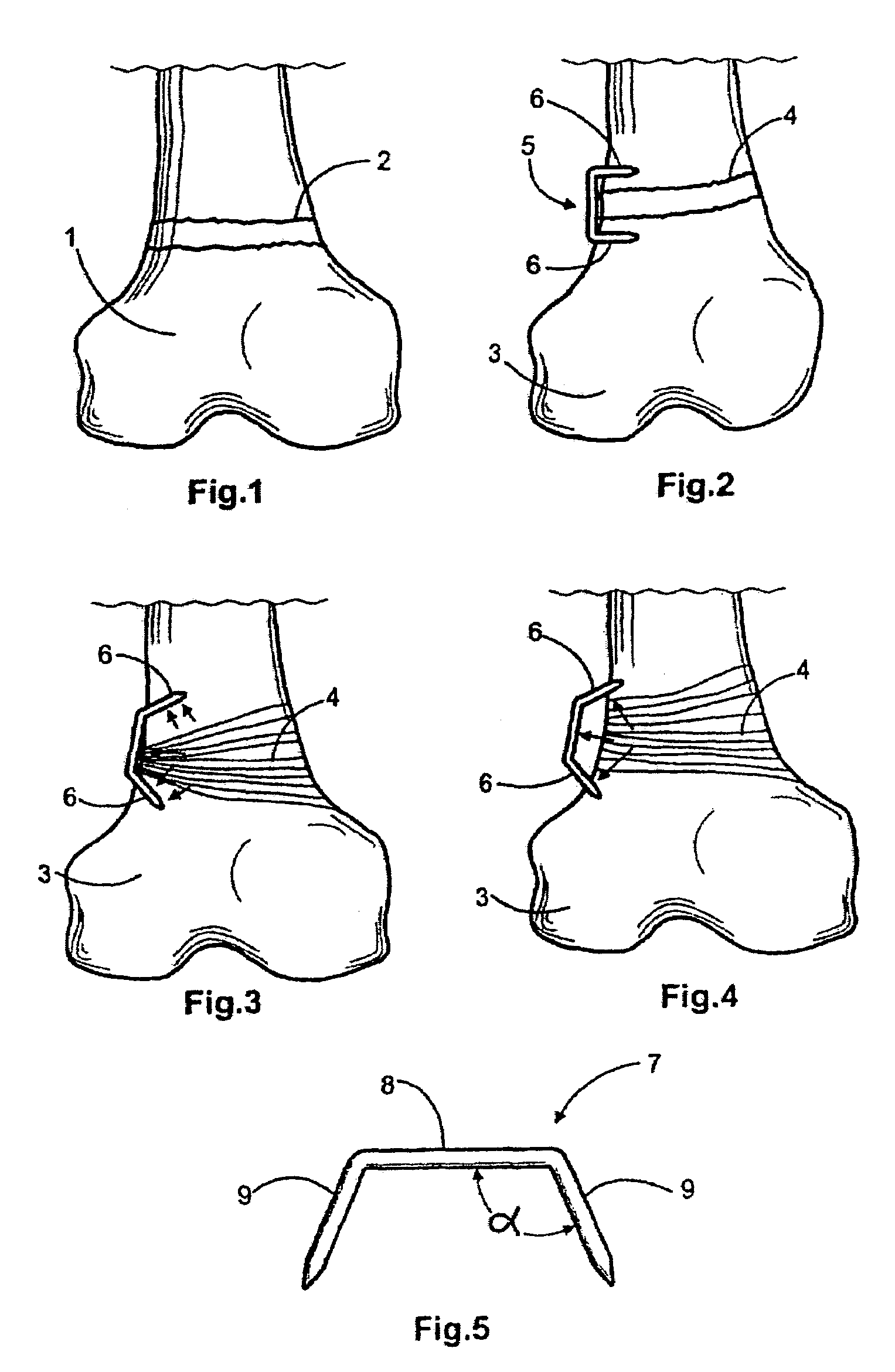
[0087]Now referring in detail to the drawings reference will be made to several alternative staples, methods for implanting the same and applications to correct different and distinct malformations and abnormalities such as in long bones, broken bones, spinal column, etc.

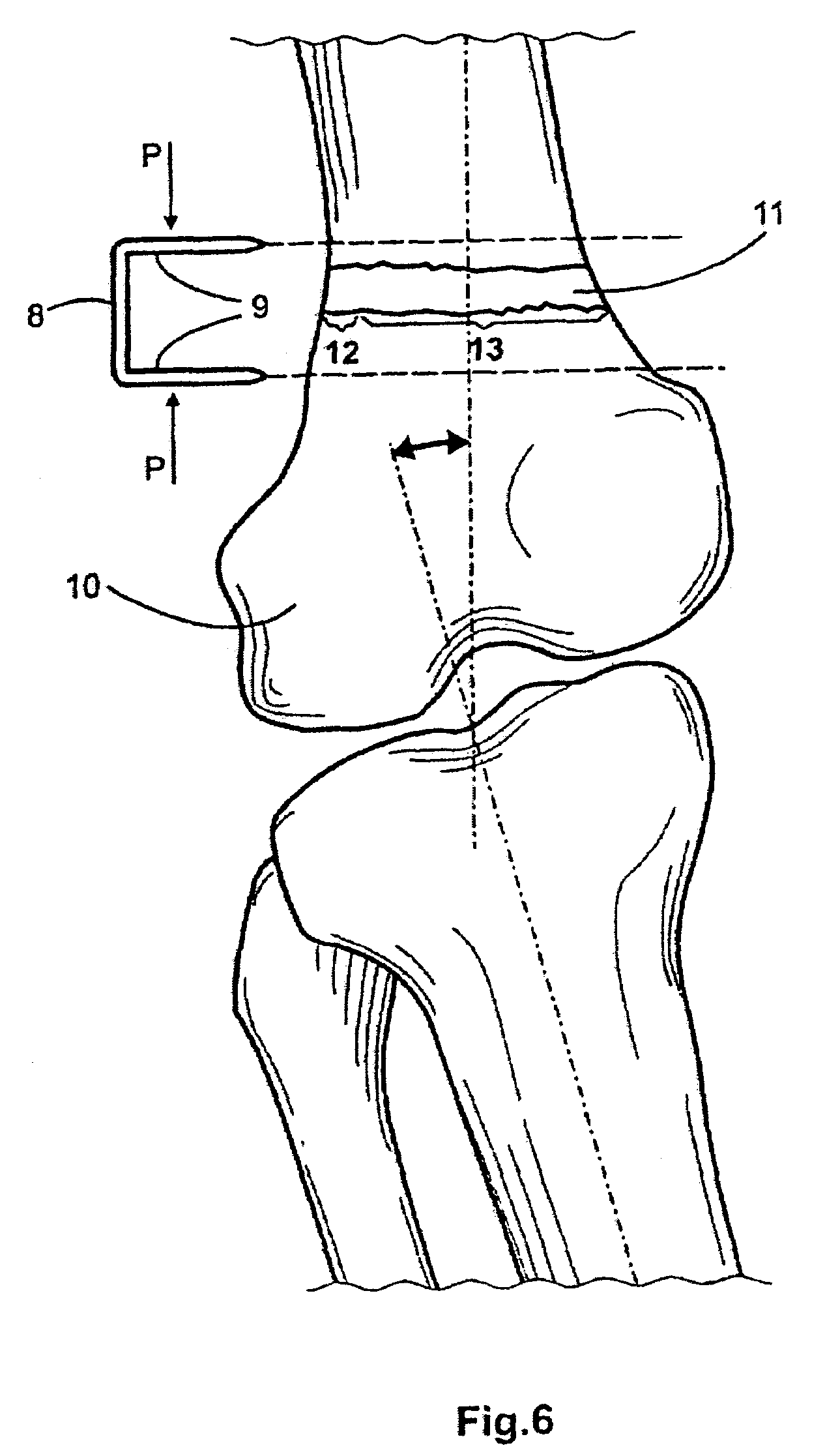
[0088]It may be seen from FIG. 1 a normal bone, particularly a femur head 1 having a normal epiphyseal or growth plate 2 whereby the femur growths normally along a normal longitudinal axis of the bone. When the bone, such as bone 3, includes an abnormal growth plate, an angled plate 4 as shown in FIGS. 2-4, for example, the bone tends to growth along a line deviated out from the normal bone axis, thus providing the bone with a convex side and a concave side. Depending of the location of this abnormalities the patient will be affected of a genu valgum or varum. FIG. 2 clearly shows that the left bottom portion or protrusion of bone 3 is larger than the right one, therefore a bottom bone (not illustrated) that is join...


PUM


Abstract

A method and staple for correcting an abnormally curved bone, such as a spinal column having a concave side and a convex side, the method comprising providing a staple having a central portion and a pair of legs with a first memorized shape and a second deformed shape and implanting the staple, in the second shape, at the convex side of the spinal column in a manner that the legs extend close to the concave side, such that the legs exert a distraction force at the concave side of the spinal column.

Description

CROSS-REFERENCE TO RELATED APPLICATIONS[0001]This application is a continuation-in-part of U.S. patent application Ser. No. 10 / 924,900, filed Aug. 25, 2004, which is a divisional of U.S. patent application Ser. No. 10 / 051,156, filed Jan. 22, 2002, now granted U.S. Pat. No. 6,966,911, issued on Nov. 22, 2005, all of which are incorporated herein by reference.BACKGROUND OF THE INVENTION[0002]1. Field of the Invention[0003]The present invention relates to the medical field and particularly to orthopaedics and traumatology for the correction of limb bone deformities, disorders and deficiencies. More particularly, the invention relates to an implant or staple and method for repairing bones and / or correcting limb inequality and most preferably the invention relates to methods and staples for correcting bone deficiencies such as abnormal curvatures by suppressing and / or inducing the growth of the bone mass and / or the epiphyseal plate in the bone. Even most particularly the invention relate...

Claims


Application Information

Patent Timeline
Patent Type & Authority Patents(United States)
IPC IPC(8): A61B17/70
CPCA61B17/0642A61B17/7011A61B17/7059A61B17/7032A61B2017/0648A61B2017/00867
Inventor GROISO, JORGE ABEL
Owner GROISO JORGE ABEL
Why Eureka
Try Eureka